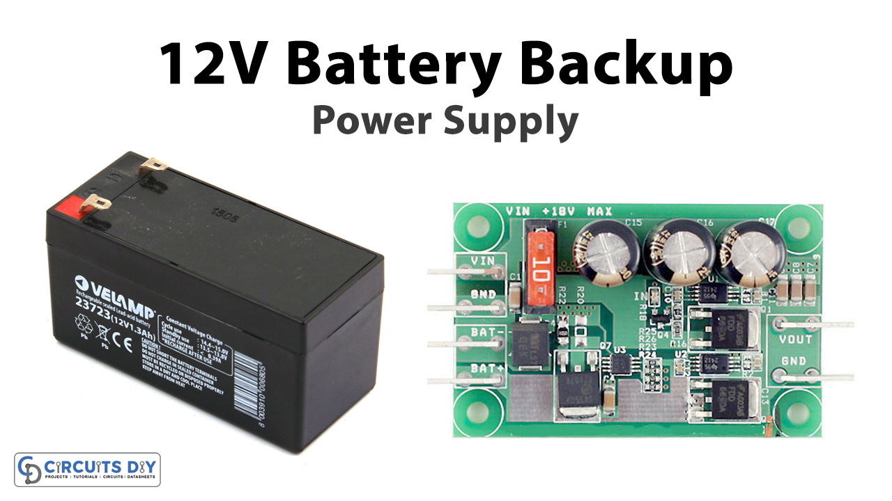
In this tutorial, we are making a circuit of a 12V Battery Backup Power Supply. This circuit will automatically shift the load to the battery in the absence of the main supply. When the mains supply is back the load will shift to the mains supply and the battery will go into charging mode automatically.
Hardware Components
The following components are required to make 12V Battery Backup Circuit
| S.no | Component | Value | Quantity |
|---|---|---|---|
| 1. | Step-down Transformer | 110V or 230V AC to 12V/1mA | 1 |
| 2. | Diode | 1N4007, 1N4148 | 6, 2 |
| 3. | Battery | 12V 7.2AH | 1 |
| 4. | Capacitor | 1000µF/50V, 330µF, 100nF | 1, 1, 1 |
| 5. | Zener diode | 9.1V | 1 |
| 6. | Transistor | 2N4401, 2N4403 | 1, 1 |
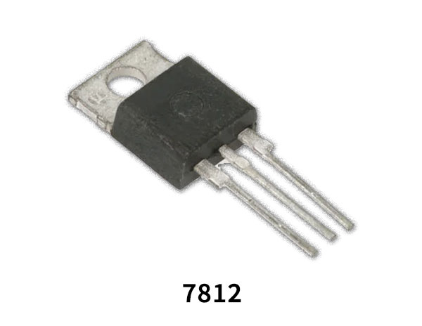
| 7. | Voltage Regulator IC | LM7812 | 1 |
| 8. | Switch | – | 1 |
| 9. | Relay | 12V | 1 |
| 10. | LED | Green | 1 |
| 11. | Resistor | 1K, 470R | 3, 1 |
| 12. | Variable Resistor | 10K | 1 |
LM7812 Pinout
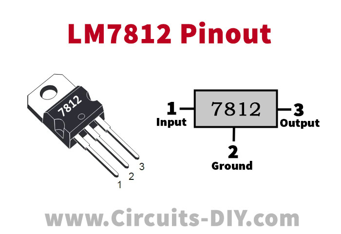
For a detailed description of pinout, dimension features, and specifications download the datasheet of LM7812
2N4403 Pinout
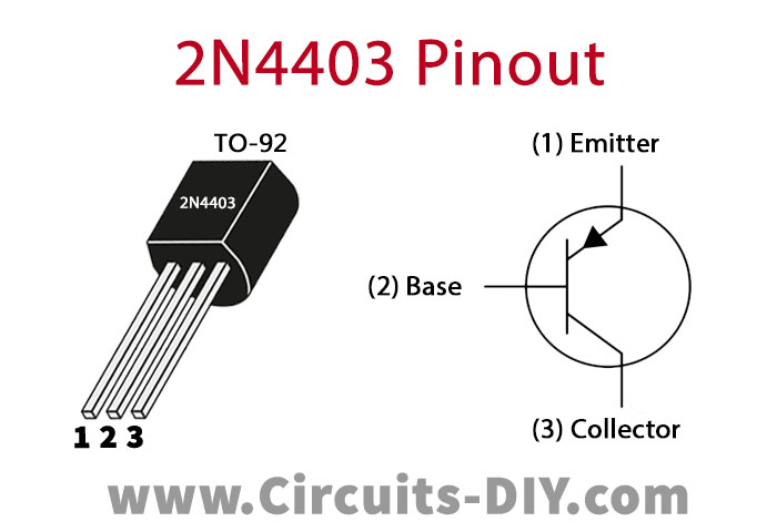
For a detailed description of pinout, dimension features, and specifications download the datasheet of 2N4403
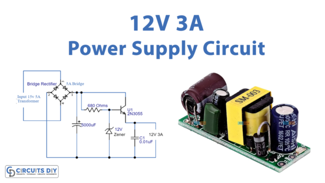
12V Battery Backup Circuit
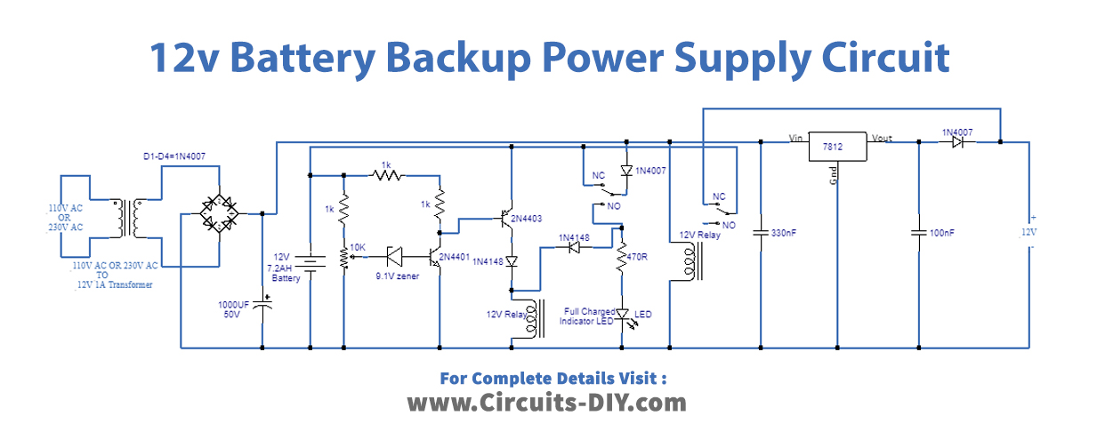
Working Explanation
This circuit has three parts, the first part is supplying power to the whole circuit. The second part is an automatic battery charger, so when the battery will become fully charged this circuit will stop charging it automatically. The green LED is used for the indication of a fully charged battery. The third part is a voltage regulator, which is providing a fixed and clean voltage of 12V by LM812 IC and smoothing capacitors.
The output current is 1A and this circuit can be used for devices that require current under 1A. We’re using a 7.2AH SLA battery but you can use 10 or 12AH for longer backup. You can also use a 20 or 25AH SLA battery and it will take a longer time to charge as compared to the others. You can modify this circuit for higher current output by using a high ampere transformer with suitable diodes in the diode bridge. And also uses a transistor with the IC to amplify the output current. In this way, the circuit will charge a higher ampere battery faster.
Circuit Adjustment
This circuit requires some adjustments initially.
- Connect an adjustable power supply.
- Set the voltage of the adjustable power supply to 14.4V. Remove the battery and the transformer and connect the power supply in the place of the battery.
- Adjust the 10K variable resistor until the LED glows.
- Connect your battery and the transformer back to where they were and remove the adjustable power supply.
- Now your circuit will go into charging mode. See if the LED lights up when the battery voltage reaches 14.4V while it’s charging. Check the voltage through a multimeter. If not adjust the variable resistor until the LED lights up.
- Now your circuit is ready to use.