Overview
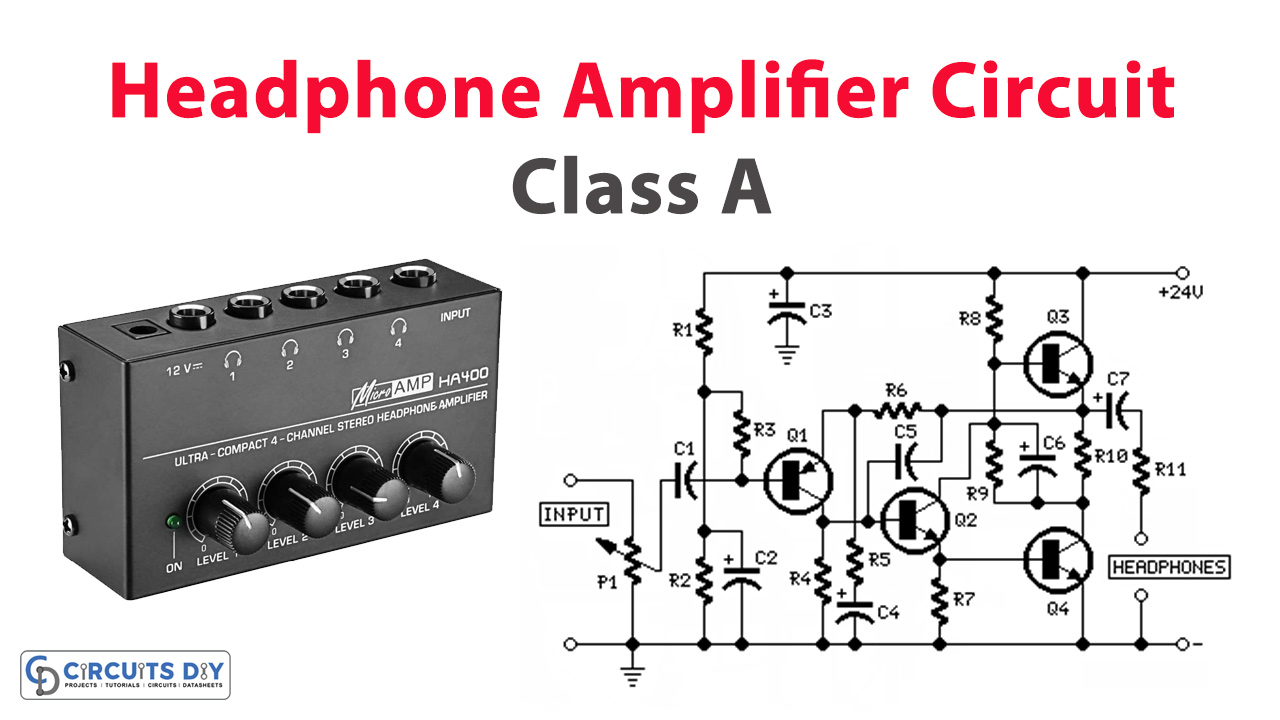
The remarkable simplicity of the 7W Class-A Audio Amplifier circuit might naturally suggest that it could be easily adapted into a Headphone Amplifier. Consequently, this adaptation was promptly executed, yielding a Headphone Amplifier capable of delivering 500mW into a 32 Ohms load. Notably, this amplifier boasts ultra-low Total Harmonic Distortion (THD), draws approximately 100mA current per channel, and incorporates compact heatsinks for the output transistors.
In today’s tutorial, we are going to make a “Headphone Amplifier Circuit” using BC560, BC337, and BD437.
Hardware Components
You’ll need the following hardware components to get started:
| S.no | Components | Value | Qty |
|---|---|---|---|
| 1 | Transistors | Q1=BC560C-45V/100mA PNP Q2=BC337-45V/800mA NPN Q3,Q4=BD437-45V/4A NPN | 1 1 2 |
| 2 | Capacitors | C2=47µF-25v C3,C6,C7=220µF-25v C4=100µF-25v C1=470nF-63V C5=47pF-63V | 1 1 3 1 1 |
| 4 | Resistors | R1,R2=47k-1/4w R3=100k-1/4w R4=8k2-1/4w R5=470R-1/4w R6=2k7-1/4w R7=1k-1/4w R8=560R-1/4w R9=100R-1/4w R10=10R-1/4w R11=22R-1/2w | 2 1 1 1 1 1 1 1 1 1 |
| 5 | Potentiometer | P1=50K Log(or 47K) | 1 |
Schematic

24VDC Power Supply Circuit
| S.no | Components | Value | Qty |
|---|---|---|---|
| 1 | Integrated Circuit IC | IC1=LM317 | 1 |
| 2 | Polar Capacitors | C1=3300µF-35v or 50v C2=10µF-25v | 1 1 |
| 3 | Resistors | R1=2K7-1/2w R2=6K8-1/4w R3=18K-1/4w R4=270R-1/4w | 1 1 1 1 |
| 4 | Diode | D1=Diode bridge 100 to 400V, 1A | 1 |
| 5 | Switch | SW1=SPST Mains | 1 |
| LED’s | D2=LED Any type and color | 1 | |
| 6 | Plug | PL1=Male Mains plug with cord | 1 |
Schematic

Notes:
- The regulated power supply circuit is straightforward and employs an LM317 3-Terminal Adjustable Regulator IC. The parts values suggested are suited to power a stereo version of this design.
- The total current drawing of each amplifier is about 100mA and should not require adjustment.
- Use small, U-shaped heatsinks for Q3 and Q4. A similar heatsink could be used also for IC1, though in most cases it is not necessary.
Technical data:
- Max output power:545mW RMS into 32 Ohms (1KHz sine wave)
- Input sensitivity:250mV RMS for 30mW output, 1V RMS for full output
- Frequency response @ 100mW RMS:Flat from 20Hz to 20KHz
- Total Harmonic Distortion @ 1KHz and 10KHz:
- 0.5mW 0.005% 1mW 0.004% 15mW 0.002% 100mW 0.002% 136mW 0.0045%
- 250mW 0.013% 500mW 0.04%

