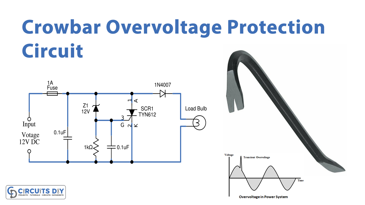
In this tutorial, we are going to make a “Crowbar Overvoltage Protection Circuit”.
It is very essential to protect the sensitive electronic or electric load from damage. For this we need protection circuits, over-voltage protection circuits, over current protection circuits, reverse supply protection circuits, or surge protection circuits. By implementing these circuits, we can ensure the protection of sensitive load. Protection of electronic components and the surroundings from high voltage is the first and most important thing to do. And therefore, engineers have designed the overvoltage protection module. Through the overvoltage protection circuit, set a specified voltage threshold when the output of power supply voltage exceeds this value, the overvoltage protection circuit activates and the power supply works to pull down the overvoltage on its output.
Here Crowbar Overvoltage Protection Module circuit is designed to protect a bulb load. It operates by putting a short circuit or low resistance path across the voltage output, very much like dropping a crowbar across the output terminals of the power supply, hence the name. By applying the voltage regulator Zener diode we can set the output voltage limit to this crowbar circuit. For example, here we took a 12V DC bulb and applied different voltages, and tested the crowbar circuit with over-voltage beyond 12 volts.
Hardware Component
The following components are required to make Crowbar Overvoltage Protection Circuit
| S.o | Component | Value | Qty |
|---|---|---|---|
| 1. | Glass fuse | 1A | 1 |
| 2. | Zener diode | 12V | 1 |
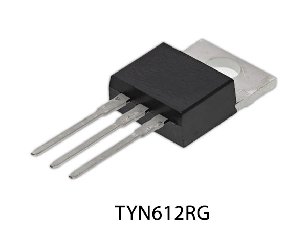
| 3. | SCR | TYN612 | 1 |
| 4. | Capacitor | 0.1µF | 2 |
| 5. | Resistor | 1KΩ | 1 |
| 6. | Diode | 1N4007 | 1 |
| 7. | DC bulb | 12V | 1 |
TYN612 Pinout
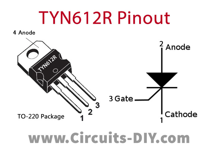
For a detailed description of pinout, dimension features, and specifications download the datasheet of TYN612
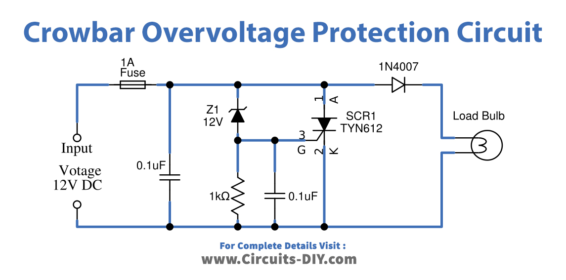
Crowbar Overvoltage Protection Circuit
Working Explanation
Attach all the components of the current values as given in the circuit properly. This prototype uses a 12V bulb as a sensitive load hence we need to design a crowbar circuit for 12V and so the 12V Zener diode regulator is placed in this circuit. This crowbar over-voltage protection circuit is designed to cut the power supply to sensitive load when over-voltage flows. It keeps the track of the input voltage and only acts when it exceeds the limit. When the limit is exceeded, the circuit causes a short circuit across the power lines and the fuse connected made of a low melting point metal, melts breaking the circuit. First, start with the glass fuse, that is used to provide safety to the circuit from overcurrent spikes. Its essential component is a metal wire or strip that is used in series to the circuit. When the current in the circuit is too high, the metal strip melts breaking the circuit.
Now place the thyristor SCR TYN612 across the load, a Thyristor has three terminals: anode, cathode, and gate. The gate controls the flow of current between anode and cathode. The primary function of the Thyristor is to control electric power and current by acting as a switch. It is mainly used as a rectifier because it can switch rapidly from a state of conducting current to a non-conducting state. When applying gate supply through the Zener diode, the Zener effect is predominant in lower voltages whereas, the avalanche breakdown happens at higher voltages. They are used to generate low-power stabilized power supplies. They are also used to protect circuits from overvoltage and electrostatic discharge. Here diode 1N4007 is used to protect reverse voltage.
By using a variable power supply unit, we have applied the power supply to this circuit and by applying voltage below 12V and up to 12V the load gets power supply and when we apply input supply beyond 12V then SCR gets gate supply through Zener diode The value of the voltage at which the short circuit happens depends upon the Zener Voltage, it makes the short circuit through Anode and Cathode pins. When the Zener voltage is exceeded, the Zener diode starts conducting and the voltage is applied to the gate terminal of the SCR. The voltage applied at the gate terminal of the SCR makes it conduct and there is a short circuit between the input voltage and the ground. This short circuit draws the maximum possible current from the circuit and blows up the fuse isolating the power supply from the load. So that the overvoltage doesn’t reach the sensitive load.
This arrangement of the circuit saves the components and the circuit itself from overshoot of voltages, by blowing up a sacrificial fuse which can be replaced very easily.
Applications
- Electronic devices
- Power transformers.
- Power supply
- Automation circuits, etc.