Introduction
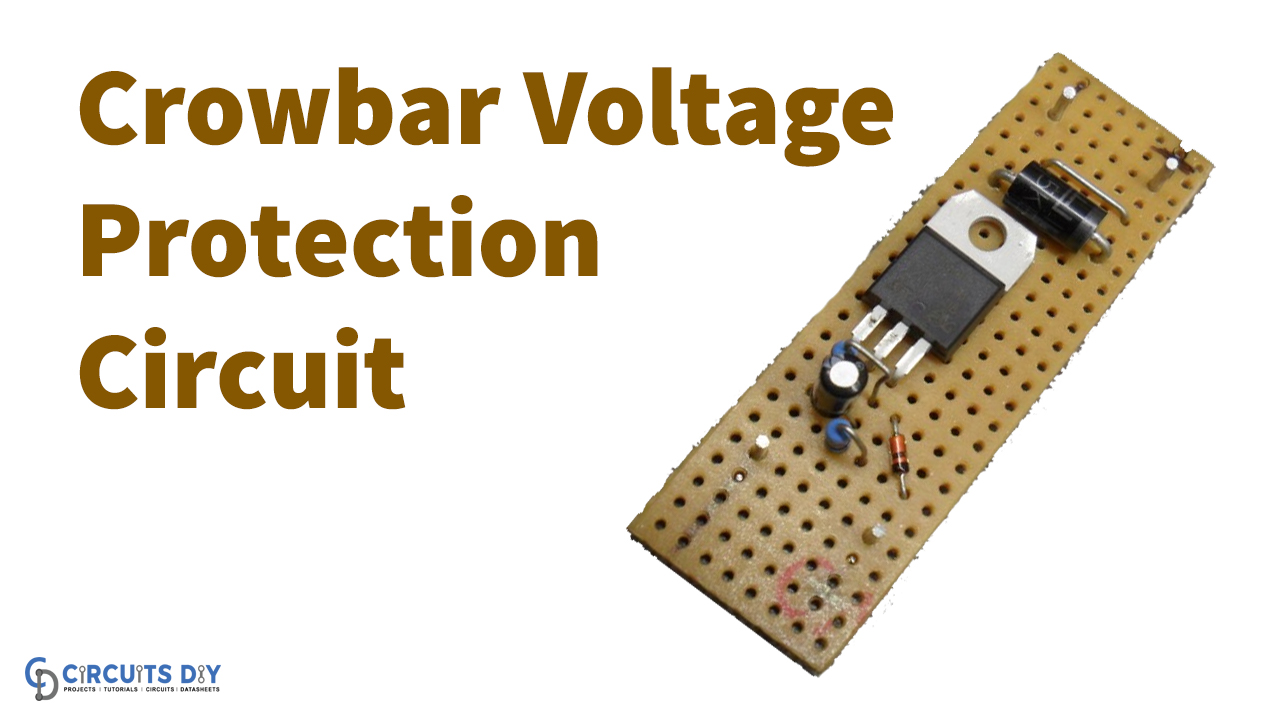
Protection of electronic components and the surroundings from high voltage is the most important thing to do. And therefore, engineers have designed the overvoltage protection module. Through the overvoltage protection circuit, it is workable to set a specified voltage threshold, when the output of the power supply voltage exceeds this value, the overvoltage protection circuit activates and the power supply works to pull down the overvoltage on its output. In this tutorial, we are going to the “Crowbar Overvoltage Protection Module”.
A Crowbar circuit checks the input voltage and whenever it exceeds the limit, it forms a short circuit and blows up the fuse. Once the fuse is blown it will disconnect the power supply from the load and therefore prevent it from high voltage. The circuit functions by making a direct short circuit across the power lines, like a crowbar are dropped between the power lines. And, therefore it is known as a crowbar circuit.
JLCPCB is the foremost PCB prototype & manufacturing company in china, providing us with the best service we have ever experienced regarding (Quality, Price Service & Time).
Hardware Components
The following components are required to make Overvoltage Protection Circuit
| S.no | Component | Value | Qty |
|---|---|---|---|
| 1. | Fuel | 1A | 1 |
| 2. | Zener diode | 12V | 1 |
| 3. | DC bulb | 12V | 1 |
| 4. | SCR | TYN612 | 1 |
| 5. | Diode | 1N4007 | 1 |
| 6. | Ceramic Capacitor | 0.1uF | 2 |
| 7. | Resistor | 1KΩ | 1 |
| 8. | 2 Pin Connector | – | 1 |
TYN612 Pinout
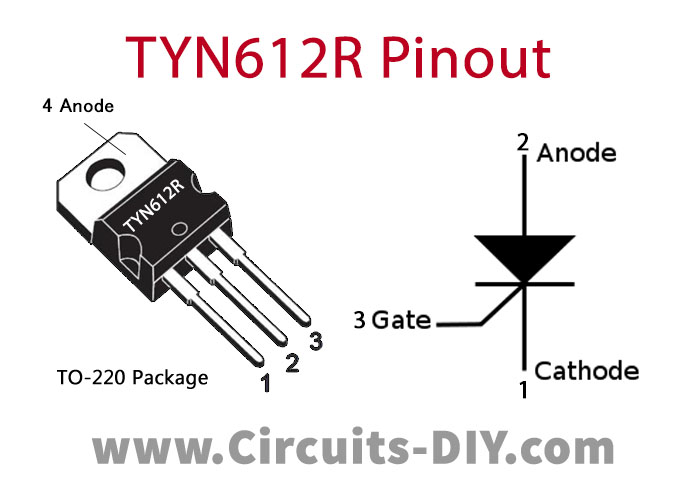
For a detailed description of pinout, dimension features, and specifications download the datasheet of TYN612
Overvoltage Protection Circuit

Working Explanation
In this Crowbar Overvoltage Protection Module since we are using a 12V bulb as a sensitive load, therefore we have to design a crowbar circuit for 12V and so we placed the 12V Zener diode regulator in this circuit. To make the circuit, set the thyristor across the load and apply the gate supply through the Zener diode. There is one more diode in the circuit, which we are using for reverse voltage protection. We are using the variable supply for the circuit. So when we apply voltage below 12V or up to 12V the load gets power. And when we give an input supply of more than 12V, then the thyristor gets gate supply through the help of the Zener diode and forms the short circuit. As a result, the overvoltage doesn’t influence the sensitive load.
Application and Uses
- Power transformers.
- Power supply
- Electronic devices
- Automation circuits, etc.

