Introduction
If you’re an avid maker or a robotics enthusiast, you’ve come across this tiny yet powerful module that combines an MPU6050 accelerometer and gyroscope, an HMC5883L magnetometer, and a BMP085 barometer. The GY-87 IMU module is a great way to add motion sensing to your projects, like a self-balancing robot or a quadcopter.
But before you can start experimenting with the GY-87 IMU module, you need to know how to interface it with your Arduino board. That’s where this blog comes in! In the following paragraphs, we’ll cover the basics of the GY-87 IMU module, how to set it up, and how to write the Arduino code to read the sensor data. We’ll also provide some tips and resources for troubleshooting common issues.
So, if you’re ready to start, let’s dive in and learn about interfacing the GY-87 IMU module with Arduino!
What is GY-87 IMU MPU6050?
Inertial measurement unit (IMU) modules like the GY-87 combine many sensors into a single package, such as the MPU6050 accelerometer/gyroscope, the HMC5883L magnetometer, and the BMP085 barometric pressure sensor. Hence, the GY-87 IMU MPU6050 is an all-in-one 9-axis motion tracking module that combines a 3-axis gyroscope, 3-axis accelerometer, 3-axis magnetometer, and a digital motion processor. It is used a lot in robotic projects, like quadcopters and other unmanned aerial vehicles (UAVs), because it can accurately measure and track orientation and motion. It is also used in other applications, such as navigation, gaming, and virtual reality.

Hardware Components
You will require the following hardware for Interfacing GY-87 IMU MPU6050 HMC5883L BMP085 Module with Arduino.
| S.no | Component | Value | Qty |
|---|---|---|---|
| 1. | Arduino UNO | – | 1 |
| 2. | MPU6050 Sensor Module | GY-87 | 1 |
| 3. | Breadboard | – | 1 |
| 4. | Jumper Wires | – | 1 |
GY-87 with Arduino
Now that you have understood the GY-87, it’s time to interface with the Arduino. To do that, follow the given steps:
Schematic
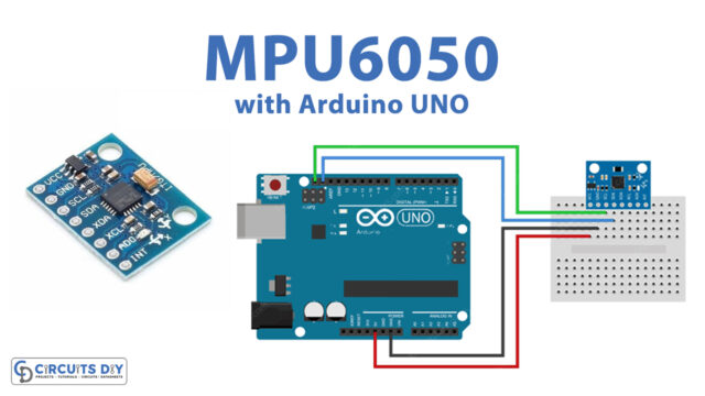
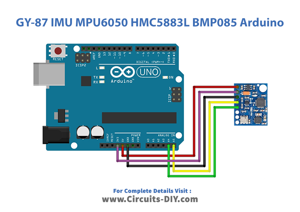
Make connections according to the circuit diagram given below
Wiring / Connections
| Arduino | MPU6050 Sensor |
|---|---|
| 5V | VCC |
| GND | GND |
| A4 | SDA |
| A5 | SCA |
Installing Arduino IDE
First, you need to install Arduino IDE Software from its official website Arduino. Here is a simple step-by-step guide on “How to install Arduino IDE.”
Installing Libraries
Before you start uploading code, download and unzip the following libraries at /Program Files (x86)/Arduino/Libraries (default) in order to use the sensor with the Arduino board. Here is a simple step-by-step guide on “How to Add Libraries in Arduino IDE.”
Code
Now copy the following code and upload it to Arduino IDE Software.
#include "I2Cdev.h"
#include "MPU6050.h"
#include <Adafruit_BMP085.h>
#include <HMC5883L_Simple.h>


MPU6050 accelgyro;
Adafruit_BMP085 bmp;
HMC5883L_Simple Compass;


int16_t ax, ay, az;
int16_t gx, gy, gz;

#define LED_PIN 13
bool blinkState = false;

void setup() {
  Serial.begin(9600);
  Wire.begin();

  // initialize devices
  Serial.println("Initializing I2C devices...");

  // initialize bmp085
  if (!bmp.begin()) {
    Serial.println("Could not find a valid BMP085 sensor, check wiring!");
    while (1) {}
  }

  // initialize mpu6050
  accelgyro.initialize();
  Serial.println(accelgyro.testConnection() ? "MPU6050 connection successful" : "MPU6050 connection failed");
  accelgyro.setI2CBypassEnabled(true); // set bypass mode for gateway to hmc5883L


  // initialize hmc5883l
  Compass.SetDeclination(23, 35, 'E');
  Compass.SetSamplingMode(COMPASS_SINGLE);
  Compass.SetScale(COMPASS_SCALE_130);
  Compass.SetOrientation(COMPASS_HORIZONTAL_X_NORTH);


  // configure Arduino LED for checking activity
  pinMode(LED_PIN, OUTPUT);
}

void loop() {
  Serial.print("Temperature = ");
  Serial.print(bmp.readTemperature());
  Serial.println(" *C");

  Serial.print("Pressure = ");
  Serial.print(bmp.readPressure());
  Serial.println(" Pa");

  // Calculate altitude assuming 'standard' barometric
  // pressure of 1013.25 millibar = 101325 Pascal
  Serial.print("Altitude = ");
  Serial.print(bmp.readAltitude());
  Serial.println(" meters");
  Serial.print("Pressure at sealevel (calculated) = ");
  Serial.print(bmp.readSealevelPressure());
  Serial.println(" Pa");
  Serial.print("Real altitude = ");
  Serial.print(bmp.readAltitude(101500));
  Serial.println(" meters");


  // read raw accel/gyro measurements from device
  accelgyro.getMotion6(&ax, &ay, &az, &gx, &gy, &gz);

  // display tab-separated accel/gyro x/y/z values
  Serial.print("a/g:\t");
  Serial.print(ax); Serial.print("\t");
  Serial.print(ay); Serial.print("\t");
  Serial.print(az); Serial.print("\t");
  Serial.print(gx); Serial.print("\t");
  Serial.print(gy); Serial.print("\t");
  Serial.println(gz);


  float heading = Compass.GetHeadingDegrees();
  Serial.print("Heading: \t");
  Serial.println( heading );


  // blink LED to indicate activity
  blinkState = !blinkState;
  digitalWrite(LED_PIN, blinkState);

  delay(500);
}
Let’s Test It
Once you upload the code, it’s time to test the circuit! The code in the Arduino program interfaces with the sensors using their libraries, which allows it to read sensor data and set various configurations of the sensors. Then it prints out the sensor data over the serial port. The LED is used to show that the circuit is doing something. This means the LED blinks every time the loop function is run, indicating that the code is actively reading sensor values.
Working Explanation
The code is the major thing on which the circuit’s working is based. So, let’s understand the code:
- First, it includes several libraries to interface with the sensors:
- “I2Cdev.h” and “MPU6050.h” are libraries for the MPU6050 6-axis accelerometer/gyroscope sensor
- “Adafruit_BMP085.h” is a library for the BMP085 barometric pressure sensor.
- “HMC5883L_Simple.h” is a library for the HMC5883L magnetometer sensor.
- Then it creates global objects for the three sensors: MPU6050 accelgyro, Adafruit_BMP085 bmp, and HMC5883L_Simple Compass.
- Next, it defines some variables to store sensor values, such as ax, ay, and az for the accelerometer of MPU6050 and to head for the magnetometer of HMC5883L. And it defines a LED_PIN constant and a blinkState variable.
- The setup() function starts a serial communication and begins I2C communication. Then it initializes the three sensors:
- The BMP085 sensor is initialized by calling the begin() method. If this returns false, indicating that the sensor could not be found, the program enters an infinite loop and prints an error message over the serial port.
- The MPU6050 sensor is initialized by calling the initialize() method and checking whether it’s working correctly. And it set the I2C bypass enabled for MPU6050.
- The HMC5883L sensor is initialized by calling some functions, such as SetDeclination, SetSamplingMode, SetScale, and SetOrientation, for setting different configurations for the sensor.
- In the loop() function, the code reads data from the three sensors and prints it out over the serial port:
- It reads temperature, pressure, altitude, and pressure at sea level from the sensor.
- It reads raw acceleration and gyroscope measurements from the MPU6050 sensor.
- It reads the heading from the HMC5883L sensor, which is the angle between the direction in which the sensor is pointing and the direction in which magnetic north lies.
- Finally, it blinks the LED to indicate activity and waits a moment before rereading the sensors.
Applications
- Navigation system
- Robotics applications
- Gaming devices, etc
Conclusion.
We hope you have found this Interfacing GY-87 IMU MPU6050 HMC5883L BMP085 Module with Arduino Circuit very useful. If you feel any difficulty making it feel free to ask anything in the comment section.


