Introduction
Today, we will explore how to interface a single-axis 1:120 TT gear motor with an Arduino microcontroller. This powerful combination of hardware and software allows you to create various projects, from simple automation to complex robots.
Imagine a world where machines move with precision and grace, performing tasks efficiently and accurately. With the power of the single-axis 1:120 TT gear motor and the versatility of the Arduino microcontroller, that world can be yours to create. Together, these two components can bring your wildest robotic dreams to reality.
What is Axis Gear Motor?
An axis gear motor is a kind of electric motor often used in industrial applications. It consists of a motor and gearbox, which together transform electrical energy into mechanical energy. While the motor itself supplies the power necessary to turn the shaft, the gearbox is what slows down the rotational speed of the motor and increases the torque it produces.

Hardware Components
You will require the following hardware for Interfacing Single Axis 1:120 TT Gear Motor with Arduino.
| S.no | Component | Value | Qty |
|---|---|---|---|
| 1. | Arduino UNO | – | 1 |
| 2. | Single Axis 1-120 TT Gear Motor | 3V-6V DC | 2 |
| 3. | H-bridge Stepper | L9110S | 1 |
| 4. | Breadboard | – | 1 |
| 5. | Jumper Wires | – | 1 |
Single Axis 1:120 TT Gear Motor with Arduino
Now, to interface Single Axis 1:120 TT Gear Motor with Arduino. you need to follow the given steps:
Schematic
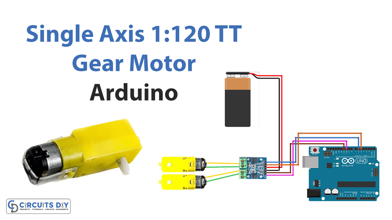
Make connections according to the circuit diagram given below.

Installing Arduino IDE
First, you need to install Arduino IDE Software from its official website Arduino. Here is a simple step-by-step guide on “How to install Arduino IDE“.
Code
Now copy the following code and upload it to Arduino IDE Software.
#define A1 5  // Motor A pins
#define A2 6
#define B1 10 // Motor B pins
#define B2 11

int incomingByte = 0; // for incoming serial data

void setup() {

  pinMode(A1, OUTPUT);
  pinMode(A2, OUTPUT);
  pinMode(B1, OUTPUT);
  pinMode(B2, OUTPUT);

  digitalWrite(A1, LOW);
  digitalWrite(A2, LOW);
  digitalWrite(B1, LOW);
  digitalWrite(B2, LOW);

  Serial.begin(9600); // opens serial port, sets data rate to 9600 bps

  Serial.println("select direction of movement");
  Serial.println("1.forward");
  Serial.println("2.backward");
  Serial.println("3.stop");

}
int  input = 0;
void loop() {

  // send data only when you receive data:
  if (Serial.available() > 0) {
    // read the incoming byte:
    incomingByte = Serial.read();
    input = incomingByte - 48; //convert ASCII code of numbers to 1,2,3

  switch (input) {
    case 1:         // if input=1 ....... motors turn forward
      forward();
      break;
    case 2:         // if input=2 ....... motors turn backward
      backward();
      break;
    case 3:         // if input=1 ....... motors turn stop
      Stop();
      break;
  }
  delay(200);
  input=0;
}
}
void forward() {          //function of forward
  analogWrite(A1, 255);
  analogWrite(A2, 0);
  analogWrite(B1, 255);
  analogWrite(B2, 0);
}

void backward() {         //function of backward
  analogWrite(A1, 0);
  analogWrite(A2, 210);
  analogWrite(B1, 0);
  analogWrite(B2, 210);
}

void Stop() {              //function of stop
  digitalWrite(A1, LOW);
  digitalWrite(A2, LOW);
  digitalWrite(B1, LOW);
  digitalWrite(B2, LOW);
}
Let’s Test It
It’s now time to test the circuit. To test the above code, you must upload it to an Arduino board. Then, you will need to open the serial monitor in the Arduino IDE and set the baud rate to 9600. Once the Serial Monitor is open, you can select one of the options (1 for forward, 2 for backward, and 3 for stopping) by typing the corresponding number. You should see the motors move forward, backward, or stop based on your input.
Working Explanation
The above Arduino program controls the movement of two motors. The program uses four digital pins (A1, A2, B1, and B2) to control the motors. The program uses the serial communication protocol to receive input from the user. The user can select three options: 1 for forward, 2 for backward, and 3 for stopping.
The input is read in the void loop() function, and the corresponding action is performed by calling the forward(), backward(), or Stop() function. The forward() function sets the A1 and B1 pins to high and A2 and B2 pins to low to make the motors move forward. The backward() function sets the A1 and B1 pins to low and A2 and B2 pins to high to make the motors move backward. The Stop() function sets all the pins to low to stop the motors.
Applications
- Automotive Applications
- conveyor systems
- Gear pumps, etc
Conclusion.
We hope you have found this Interfacing Single Axis 1:120 TT Gear Motor with Arduino Circuit very useful. If you feel any difficulty in making it feel free to ask anything in the comment section.

