

In this project
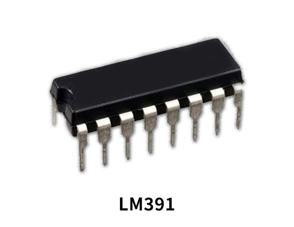
The LM391 audio power driver is designed to drive external power transistors in 10 to 100-watt power amplifier designs. High power supply voltage operation and true high fidelity performance distinguish this IC. The LM391 is internally protected for output faults and thermal overloads; circuitry providing output transistor protection is user-programmable.
LM391 Pinout
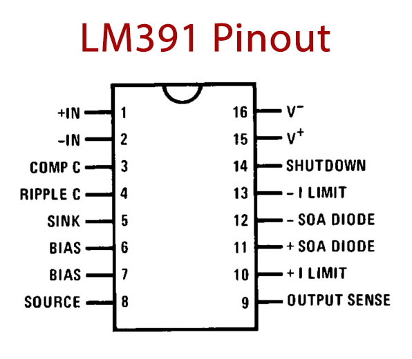
LM391 Pin Configuration
| Pin No | Pin Name | Description |
|---|---|---|
| 1 | +IN | Audio input |
| 2 | -IN | Feedback input |
| 3 | COMP C | Sets the dominant pole |
| 4 | RIPPLE C | Improves negative supply rejection |
| 5 | SINK | Drives output devices and is an emitter of AB bias VBE multiplier |
| 6 | BIAS | The base of the VBE multiplier |
| 7 | BIAS | Collector of VBE multiplier |
| 8 | SOURCE | Drives output devices |
| 9 | OUTPUT SENSE | Biases the IC and is used in protection circuit |
| 10 | + 1 LIMIT | The base of the positive side protection circuit transistor |
| 11 | +SOA DIODE | The diode used for dual slope SOA protection |
| 12 | -SOA DIODE | The diode used for dual slope SOA protection |
| 13 | - 1 LIMIT | The base of the negative side protection circuit transistor |
| 14 | SHUTDOWN | Shuts off the amplifier when current is pulled out of the pin |
| 15 | V+ | Positive supply |
| 16 | V- | Negative supply |
LM391 Key Features
- High Supply Voltage g50V max
- Low Distortion 0.01%
- Low Input Noise 3 mV
- High Supply Rejection 90 dB
- Gain and Bandwidth Selectable
- Dual Slope SOA Protection
- Shutdown Pin
Application
You can download this datasheet for LM391 Audio Power Driver - Datasheet from the link given below:
Discussion
Be the first to comment