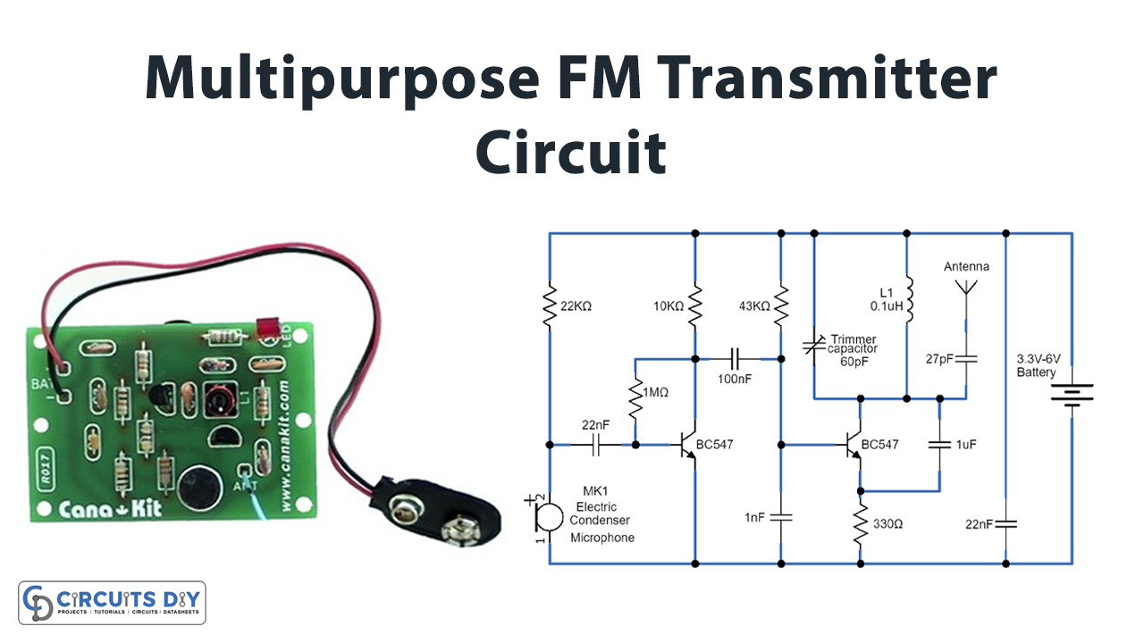
In this tutorial, we are going to make a “multipurpose FM transmitter circuit”.
The FM (frequency modulation) transmitter is a low-power transmitter, in frequency modulation, the data is transferred by varying the frequency of carrier waves and it uses FM waves for transmitting the sound/data, this transmitter transmits the audio signals through the carrier wave by the difference of frequency. We design a simple multipurpose FM transmitter circuit by using two NPN transistors and a few easily available components. The performance and working of the wireless audio transmitter circuit depend on the induction coil & variable capacitor, this circuit oscillates up to 100 MHz and you can tune and adjust the oscillating frequency by varying Trim Capacitor.
FM receiver should have the tuning frequency range according to your transmitter circuit. If your commercial FM receiver doesn’t have a frequency range then you need to make the FM receiver comply with the transmitter frequency. Always use a free FM band for your practice.
Hardware Components
The following components are required to make FM Transmitter Circuit
| S.no | Component | Value | Qty |
|---|---|---|---|
| 1. | Resistor | 22KΩ, 1MΩ, 10KΩ, 43KΩ, 330Ω | 1,1,1,1,1 |
| 2. | Transistor | BC547 | 2 |
| 3. | Trim Capacitor | 60pF | 1 |
| 4. | Ceramic Capacitor | 22nF, 100nF, 1nF, 1μF, 27pF, 22nF | 1,1,1,1,1,1 |
| 5. | Inductor | 0.1μH | 1 |
| 6. | Connecting Wires | – | 1 |
| 7. | Power Supply | 3V to 5V | 1 |
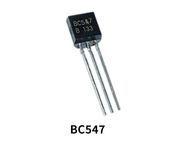
BC547 Pinout

For a detailed description of pinout, dimension features, and specifications download the datasheet of BC547
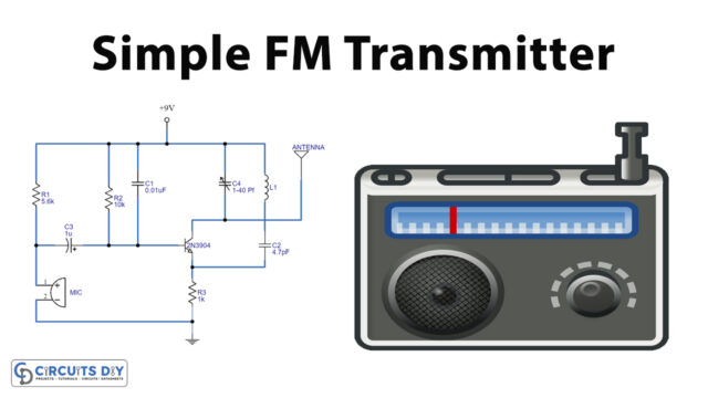
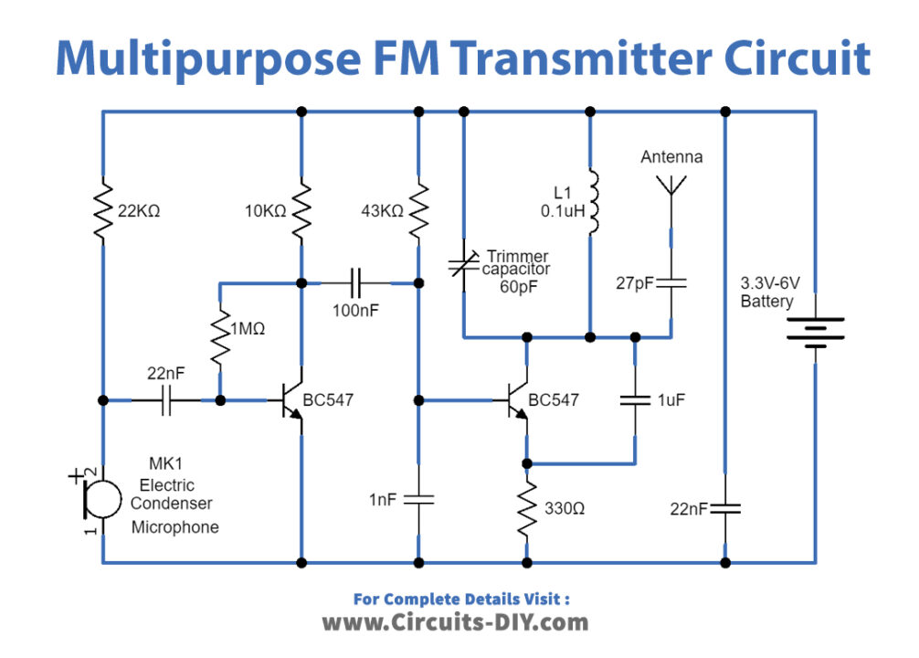
FM Transmitter Circuit
Working Explanation
This multipurpose FM transmitter circuit can be built on a compact size PCB, and there is no signal interference due to well-placed filter capacitors. To construct this circuit, start with Electret condenser microphone and apply bias through R1 Resistor, then connect output signal from mic to Q1 transistor base terminal through C1 and R2 elements. The audio output signal from the microphone is usually small, the first transistor thus performs the job of amplifying that signal to a level good enough for transmission. here the audio signal gets amplified and then output is applied to the Q2 transistor base terminal through the C2 capacitor and R4 bias Resistor.
After amplification as described earlier, the next stage of the FM transmitter is modulation. Q2 transistor has an Oscillator circuit here the audio signal is being modulated into an FM (Frequency modulation) signal. At this stage, the amplified audio signal is then mixed with the carrier frequency with which the signal is to be transmitted. This carrier frequency can be varied using the 60pF variable capacitor connected with the inductor. The output signal from the Q2 collector and tank circuit is connected to the Antenna. To make L1 we need 22 SWG copper wire and make 5 to 6 turns in the diameter of a normal pencil. For the experimental purpose here, we used an antenna without any signal booster circuit. If you want to transmit FM signal to long-range then use a proper antenna and signal booster circuit.
Applications
- This circuit can be used as a voice transmitter or audio signal transmitter by adding an Encoder and Decoder at the receiver we can transmit digital data also.
- Usually, personal FM transmitters are plugged into the audio device, let’s say an MP3 player and then the frequency for the broadcasting is selected.
- The FM transmitters are used in the homes like sound systems in halls to fill the sound with the audio source.
- These are also used in cars and fitness centers.
- The correctional facilities have used FM transmitters to reduce the prison noise in common areas.