
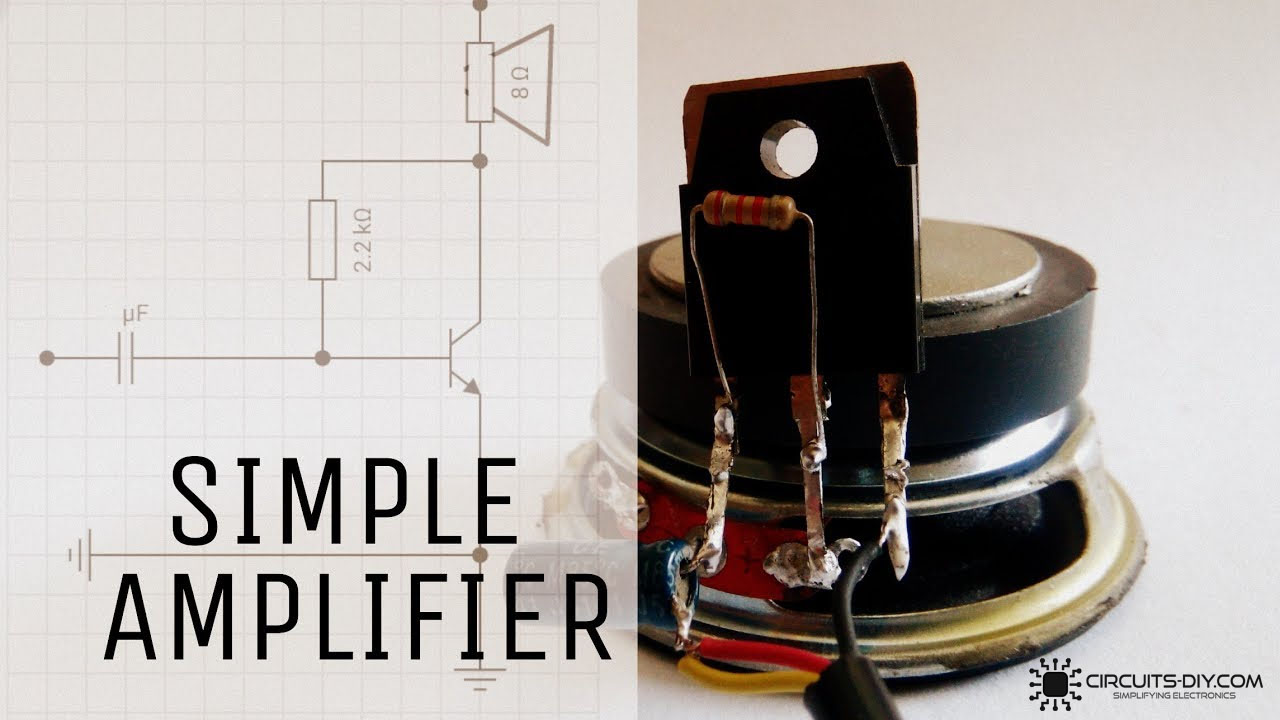
In this project
An Audio amplifier is a simple electronic circuit that boosts a low-power AC audio signal to a level where it is strong enough to be driven by an audio transducer such as a headphone or loudspeaker. Audio amplifiers have proven their worth in today's electronics, whether it be a simple toy or a complex music production process. So, in this project, we are going to design a Simple Audio Amplifier Circuit Using 2SC2625 Transistor.
The heart of this circuit is a 2SC2625 Power Transistor. 2SC2625 is a High Voltage High-Speed Switching Transistor. It is an NPN transistor in a TO-39 packaging, offering a max collector-base voltage of 450V & a collector current dissipation of 80W, thus using an appropriate heat sink during transistor operation.
Hardware Component
The following components are required to make Audio Amplifier Circuit
| S.no | Component | Value | Qty |
|---|---|---|---|
| 1. | Loudspeaker | 3W | 1 |
| 2. | Power MOSFET | 2SC2625 | 1 |
| 3. | DC Jack | male | 1 |
| 4. | Resistor | 2.2K | 1 |
| 5. | Capacitor | 47uF/10V | 1 |
| 6. | Soldering Iron | 45W - 60W | 1 |
| 7. | Soldering wire & flux | - | 1 |
| 8. | DC Battery | 3.7V | 1 |
| 9. | Suitable Audio input | smartphone | 1 |
2SC2625 Pinout
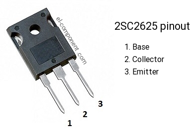
For a detailed description of pinout, dimension features, and specifications download the datasheet of 2SC2625
Audio Amplifier Circuit

Useful Steps
Follow the steps as shown in the video above.
1) Solder the 2.2K Ohm resistor to the collector-base terminal of the transistor.
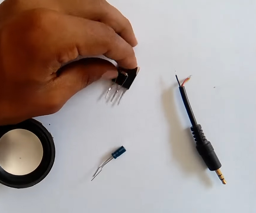
2) Solder the +ve terminal of the 47uF capacitor with a base of the transistor.
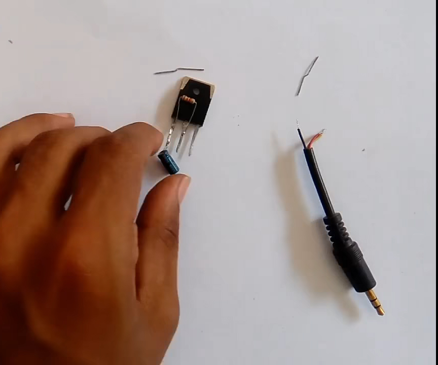
3) Solder the +ve terminal of the 3W speaker to the collector of the transistor.
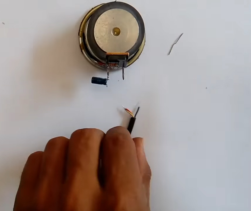
4) Solder the -ve terminal of the DC power jack to the emitter of the transistor & the other terminal to the capacitor.
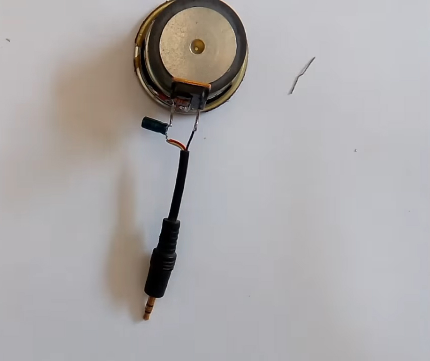
5) Connect a 3.7V Battery to the +ve terminal of the loudspeaker, and connect the -ve terminal to the emitter of the transistor.
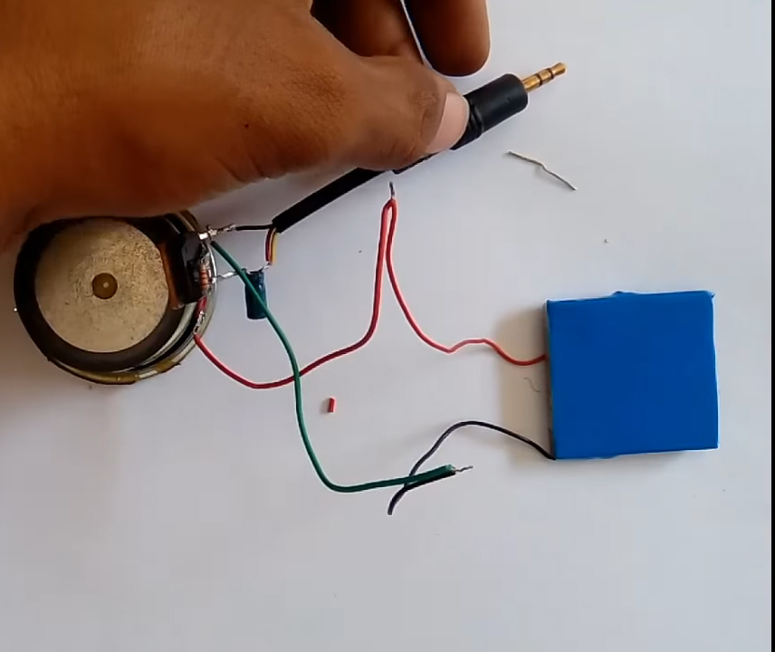
6) connect the DC Jack to an audio input & test the circuit.
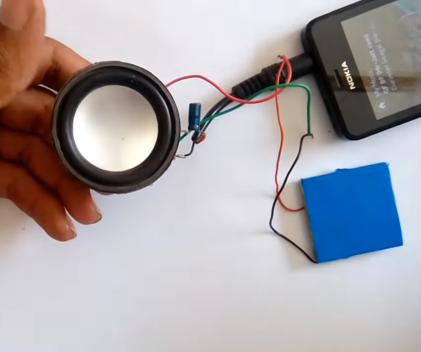
Working Explanation
The working of this circuit is quite simple. An Ac audio input is taken from a device such as a smartphone as input to the circuit. Here, a Capacitor (47uF) blocks the DC component of the signal, allowing only AC to pass through, which acts as a control signal to the base of the transistor (2SC2625).
The collector output of the transistor then goes to an audio transducer such as a loudspeaker to be generated as an audio output.
Applications
- Usually used in small toys, media players & small electronic projects.

Discussion
Be the first to comment