In this video, we will learn to make a Latching circuit using a 555 Timer IC. This Latch circuit can be drawn in several ways but we are using 555 Timer IC. In the inner configuration of this IC flip flop and comparator circuit are present which helps the circuit to behave like a toggle switch

Hardware Components
The following components are required to make a Simple Latching Circuit
| S. No | Components | Value | Qty |
|---|---|---|---|
| 1. | Breadboard | – | 1 |
| 2. | Battery | 9v | 1 |
| 3. | Switch | SPDT | 1 |
| 4. | IC | NE555 Timer | 1 |
| 5. | Resistors | 10k, 100k, 1k | 2, 1, 1 |
| 6. | Capacitor | 1uF | 1 |
| 7. | LED | – | 1 |
555 IC Pinout

For a detailed description of pinout, dimension features, and specifications download the datasheet of 555 Timer
Latching Circuit Diagram
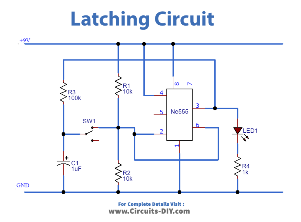
Working Explanation
The latching circuit is a logic circuit having two inputs known as a set and reset. The latch circuits are of two types. Active High in which input is set to ground and latch is triggered by high signals. Active Low in which input is set to high and latch is triggered by low signal.
The above circuit works as a toggle switch. It has two states High and low. This device will remain on unless you push it to reset and similarly will remain off unless you set it. It works like a Flip Flop. This circuit is made up of 555 Timer IC which will et it ON and the button is to be pressed to change the state.
Application
- Latches are used to encode binary numbers
- They are used in data storage as they are single-bit storage elements
- Latches are used as storage devices.