
In this project
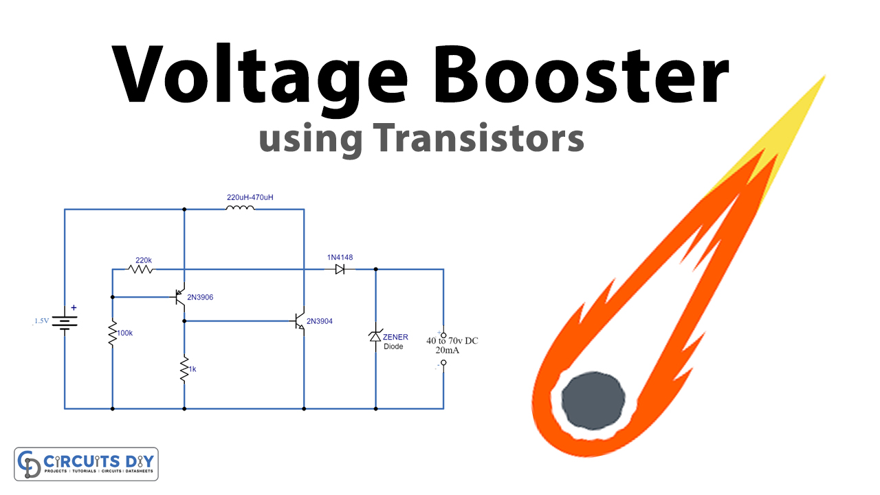
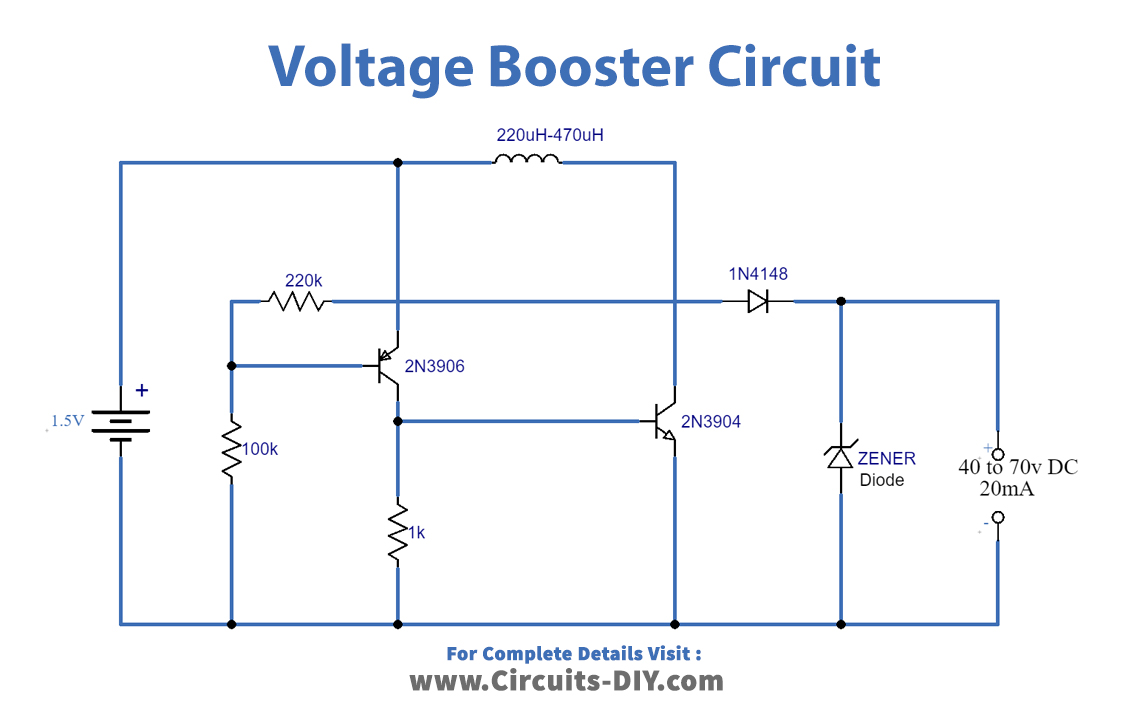
A DC Voltage booster circuit boosts a low-level DC signal, namely 1.5V to 3V to a significantly higher DC level. they commonly serve in applications requiring a much higher DC power input (about 60V to 80V DC). So, in this project, we are going to design a simple & inexpensive voltage booster circuit using transistors.
Basically, DC-DC converters/boosters are electronic circuits that step up or step down the DC voltage to get the desired voltage level. In many industrial applications, requirements tend to convert a fixed voltage DC source into a variable voltage DC source. A DC converter can be considered as a DC equivalent to an AC transformer with a continuously variable turn ratio. Like a transformer, it can step-down or step-up a DC voltage source. DC converters can also serve as switching mode regulators to convert a DC voltage, normally unregulated, to a regulated DC output voltage.
Hardware Components
The following components are required to make Voltage Booster Circuit
| S.no | Component | Value | Qty |
|---|---|---|---|
| 1. | Breadboard | - | 1 |
| 2. | Zener Diode | - | 1 |
| 3. | Battery | 1.5V | 1 |
| 4. | Transistor | 2N3906, 2N3904 | 1 |
| 5. | Resistor | 200KΩ, 100KΩ, 1KΩ | 1 |
| 6. | Inductor | 200μH - 470μH | 1 |
| 7. | Diode | 1N4148 | 1 |
2N3904 Pinout
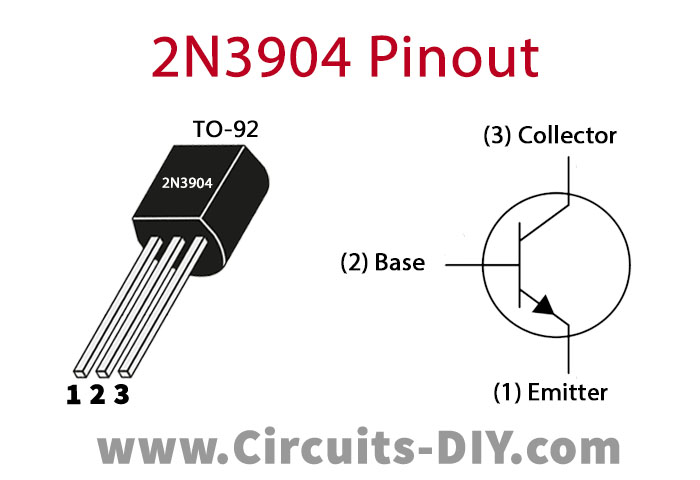
For a detailed description of pinout, dimension features, and specifications download the datasheet of 2N3904
2N3906 Pinout
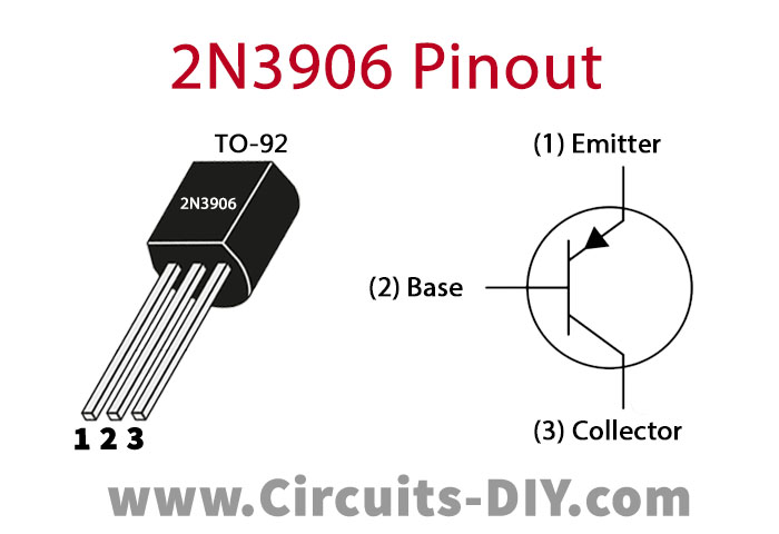
For a detailed description of pinout, dimension features, and specifications download the datasheet of 2N3906
Voltage Booster Circuit
Working Explanation
This simple voltage booster circuit can boost the voltage of a 1.5V AA battery to 40V to 70V DC. The output current of the circuit is around 20mA. The circuit can work for any application requiring a high voltage & low current input. The output depends on the inductive coil used. For example, with a 220μH coil, the max output of the circuit will be around 40V DC. Similarly, a 470μH coil can yield up to 70V DC.
The desired voltage level can be achieved by connecting a Zener diode in parallel to the output terminals. For example, if you want 18V DC then you can use an 18V Zener diode.
Applications
- Commonly used in devices such as domestic appliances & small machines
- used for processes such as pulse creation for academic & research purposes.
Discussion
Be the first to comment