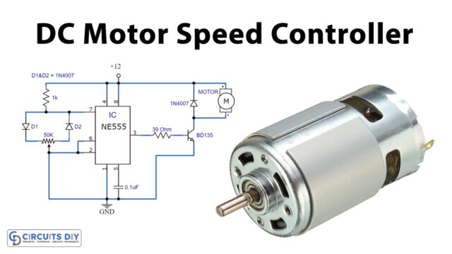
In this tutorial, we are going to make a “Stepper Motor Controller Circuit”.
When you want a specific amount of rotation stepper motors are needed. The name of this motor is given so because the rotation of the shaft is in step form which is different from DC or any other motor. In other motors, the speed of rotation, and the stop angle are not in complete control unless a necessary circuit is inserted. This non-control is present because of the moment of inertia, For the stepper motor to work properly and non-stop we need a stepper motor controller. So here we design a simple 555 timer stepper motor controller circuit with a few easily available components, it makes the stepper motor drive continuously without any interruption or step stop.
This circuit has two stages, the first one is used to generate square pulse oscillation and another one is for providing a stepping pulse to the stepper motor. Now we can drive unipolar stepper motors with different voltage ratings by using this circuit. If you want to drive higher than 12V stepper motors then add an external power source to the stepper motor and power switching transistors, because this circuit uses only a 9V power supply and is capable of driving stepper motors under 12V.
Hardware Required
| S.no | Component | Value | Qty |
|---|---|---|---|
| 1. | IC | CD4017 | 1 |
| 2. | Transistors | BC547 | 4 |
| 3. | IC | NE555 Timer | 1 |
| 4. | Diode | 1N4007 | 4 |
| 5. | Capacitor | 1uF , 0.01uF | 1,1 |
| 6 | Resistor | 1KΩ , 2KΩ | 2,1 |
| 7. | Variable Resistor | 100KΩ | 1 |
| 8. | Stepper Motor | – | 1 |
| 9. | Connecting Wires | – | – |
| 10. | Battery | 9V | 1 |
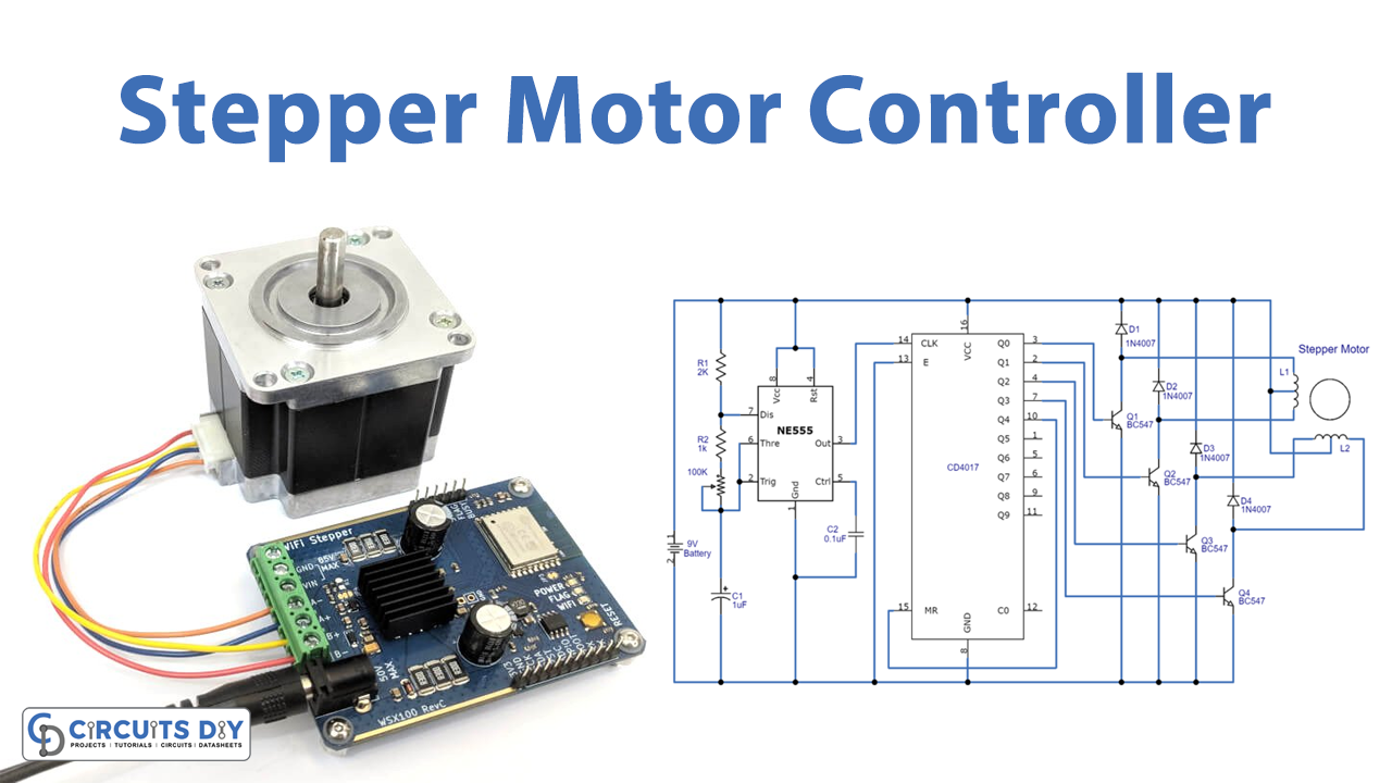
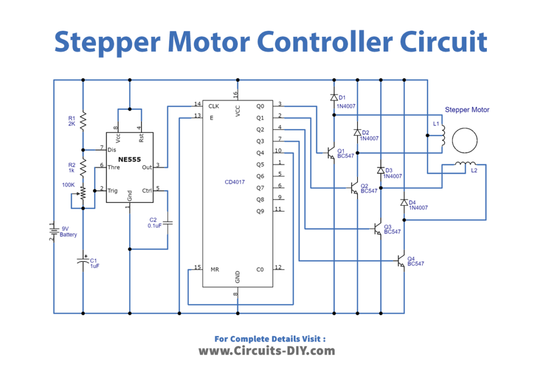
Circuit Diagram
Stepper motor
Stepper motors are DC motors that move in discrete steps. This motor is also known as a stepping motor and mostly it is a brushless DC electric motor that divides its full rotation into a number of equal steps. They have multiple coils that are organized in phases. By energizing each phase in sequence, the motor will rotate, one step at a time. The stepper motor does not work on constant supply. It can only be worked on controlled and ordered power pulses. With computer-controlled stepping, you can achieve very precise positioning and/or speed control. For this reason, stepper motors are the motor of choice for many precision motion control applications like 3D printers, CNC machines, automatic doors, etc.,
This stepper motor is divided into two categories based on its stator winding UNIPOLAR and BIPOLAR stepper motors.
Bipolar Stepper motor

In the BIPOLAR stepper motor, we have phase ends and no center taps. So, the bipolar stepper motor has a single winding per phase and only 4 leads to connect two sets of internal electromagnet coils. The driving of this type of stepper motor is different and complex and also the driving circuit cannot be easily designed without a microcontroller. Hereby changing the direction of current through the motor coils forward and reverse steps can be achieved, this might more complicated than unipolar but the H-bridge and stepper motor driver circuits make it very simple.
Unipolar Stepper motor

In a UNIPOLAR stepper motor, we can take the center tapping of both the phase windings for common ground or common power. Here the unipolar comes with 5, 6, and 8 leads and operates one winding with the center tap per phase of input. This image shows different types of unipolar stepper motors and its leads configuration. In the first case, black is taken as a common. In case 2 we can take black and white for common ground or power. In case 3 orange black red yellow all come together for common ground or power. To know further refer datasheet of your stepper motor.
Working Explanation
The circuit diagram has a two-stage stepper motor driver. Here the timer IC 555 works as an astable multivibrator to generate a clock or a square wave. And produced a square pulse based on the timing resistor and timing capacitor. The frequency of clock generation, in this case, cannot be kept constant so we need to get a variable speed for the stepper motor. To get this variable speed a preset is placed in series with a 1K resistor in a branch between the 6th and 7th pin.
The second stage is the decade counter IC CD4017 stage and this integrated circuit counts the square pulses from the timer IC and provides stepping pulse output through Q0, Q1, Q2, and Q3 output pins. Each pulse is fed into the stepper motor coil through switching transistors BC547. The diodes placed here are to protect the transistors from inductive spiking of the stepper motor winding. If these are not placed one might risk blowing the transistors. Greater the frequency of pulses, the greater the chance of blow-up without diodes. As the preset is set to a value for a certain frequency of pulses. This clock is fed to the decade counter to get regular outputs from it. The outputs from the decade counter are given to transistors to drive the high-power coils of the stepper motor in sequential order. The tricky part is, once a sequence is a complete say 1, 2, 3, 4 the stepper motor completes four steps and so it is ready to start again however the counter can go for 10 and so it goes on without interruption. If this happens the stepper motor must wait till the counter completes its cycle of 10 which is not acceptable. This is regulated by connecting RESET to Q4 so when the counter goes for five counts it resets itself and starts from one, this starts the sequence of the stepper. Hence when the pulse and power supply are applied to the stepper motor then its rotor starts to rotate, and the speed of the rotor can be varied by VR1 Resistor.
Applications
- They are used in the numeric control of machine tools.
- Used in tape drives, floppy disc drives, printers, and electric watches.
- The stepper motor is also used in X-Y plotter and robotics.