In this tutorial, we are going to make one of the simplest projects of a temperature-controlled fan. When there will be changes in the temperature this circuit will turn on and off a DC fan accordingly. This circuit has a lot of applications in everyday life as well as in electronic projects. The main component of this circuit is an op-amp IC i.e., LM741. LM741 has low power consumption and is provided with short circuit and overload protection. For temperature sensing purposes we have used a thermistor.
Thermistors are devices that detect temperature and their resistance changes with temperature. when the temperature rises its resistance decreases and increases when the temperature is decreased.
Hardware Components
| S.no | Component | Value | Quantity |
|---|---|---|---|
| 1. | Thermistor | NTC 10K | 1 |
| 2. | Variable Resistor | 10KΩ | 1 |
| 3. | Resistor | 10KΩ, 1KΩ, 1.5KΩ | 2, 1, 1 |
| 4. | IC | LM741 | 1 |
| 5. | Transistor | BD135 | 1 |
| 6. | Input Supply DC | 12V | 1 |
| 7. | DC Fan | 12V | 1 |
| 8. | Diode | 1N4007 | 1 |
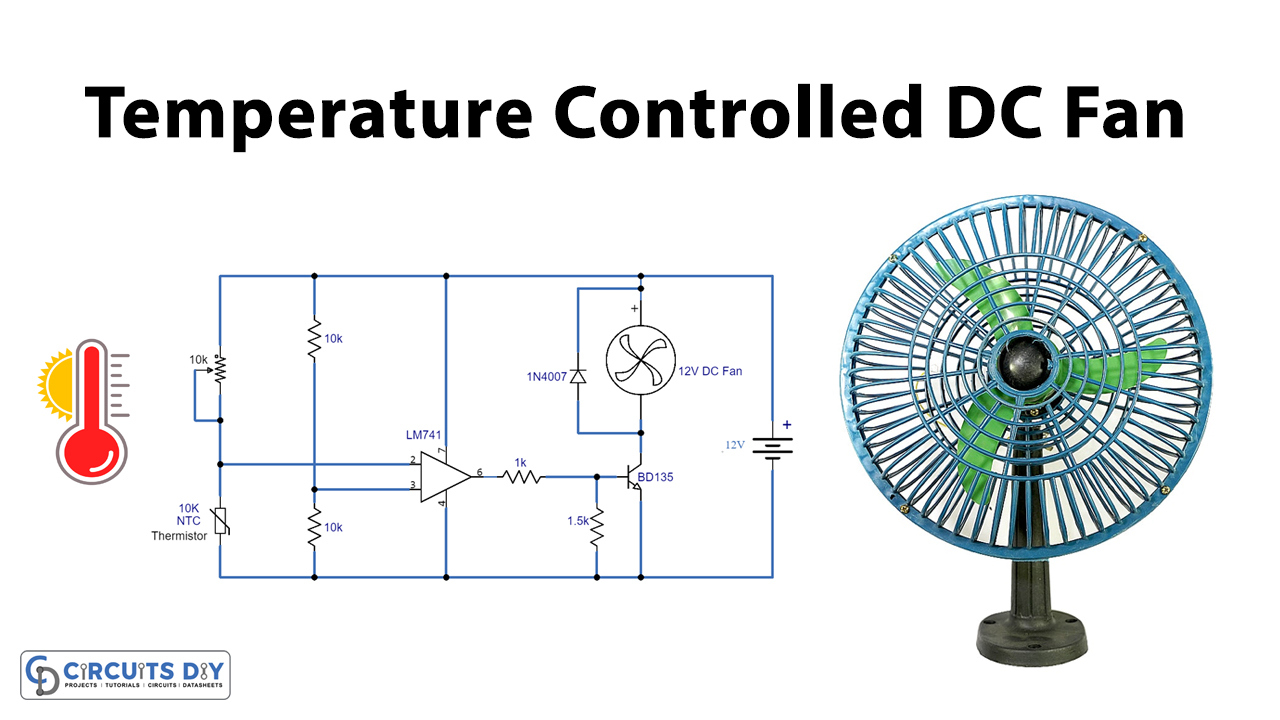
Circuit Diagram
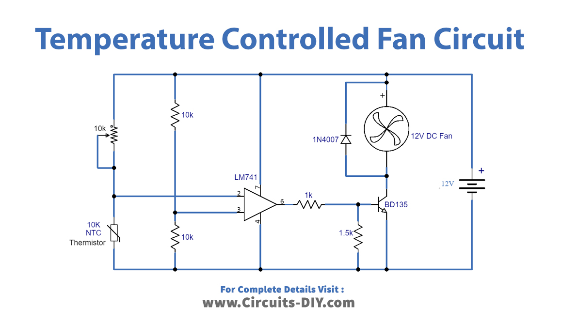
Working Explanation
When the 10K NTC thermistor senses heat its resistance will be decreased and it will power the circuit. A 10K variable resistor is used to set the circuit to activate the DC fan at your desired temperature. When the IC LM741 receives the input signal it turns on the transistor which amplifies the signal and turns on the fan. The reason for not operating the fan directly with the IC is because LM751 is only a few milliamperes therefore we had to use a BD135 transistor that can handle up to 1A load.
The transistor will dissipate heat during this operation so there should be some distance between the transistor and thermistor in the circuit so that it works properly and use a heatsink with a transistor.
Applications and uses
This can be used in various projects where cooling is required
- Power supply circuits
- Audio amplifier circuits
- Battery chargers
- PC, Laptops, etc.