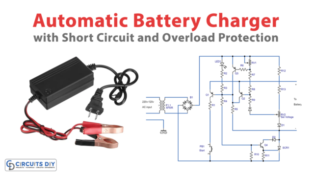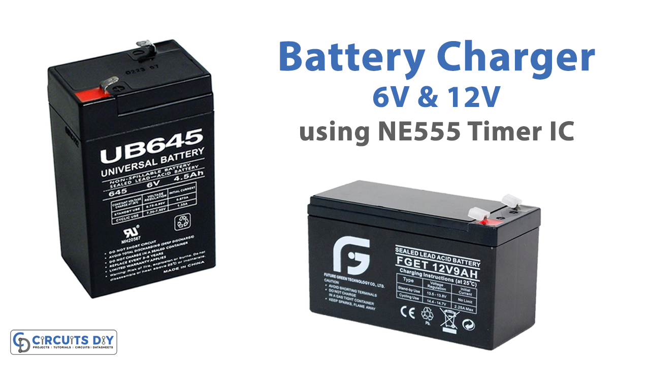
In this tutorial, we are making a project of 6V & 12V Battery Charger With an Auto Battery Detect Function. Usually, charger circuits have a single voltage output which is limited to the battery of that voltage only. Like a 12V charger will charge only 12V batteries. But this circuit can charge both 6V and 12V batteries. It is able to detect the voltage of the battery and selects the required input voltage to charge the battery automatically.

Hardware Components
The following components are required to make Battery Charger Circuit
| S.no | Component | Value | Quantity |
|---|---|---|---|
| 1. | Power Supply | 18V/2A DC | 1 |
| 2. | Zener diode | 3.3V, 9V | 1, 1 |
| 3. | Phototransistor | PC817 | 1 |
| 4. | Relay | – | 1 |
| 5. | Capacitor | 0.1µF, 1µF/50V, 10nF | 1, 1, 1 |
| 6. | Resistor | 1K, 10K, 470R, 240Ω, 2.2K | 6, 2, 1, 1, 1 |
| 7. | Potentiometer | 50K | 1, 2 |
| 8. | Diode | 1N4007 | 3 |
| 9. | Transistor | BC517, 2N4401, 2N4403, 2N3904 | 2, 2, 1, 3 |
| 10. | IC | NE555 Timer | 1, 1 |
| 11. | Voltage Regulator IC | LM317 | 1 |
| 12. | Variable Resistor | 5K | 2 |
NE555 IC Pinout

For a detailed description of pinout, dimension features, and specifications download the datasheet of 555 Timer
LM317 Pinout
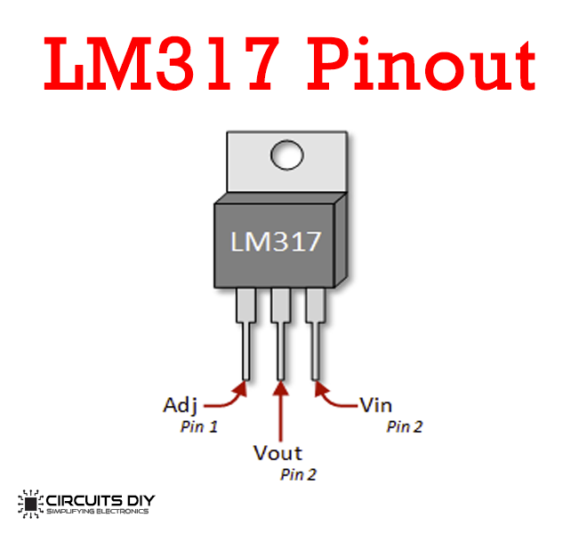
For a detailed description of pinout, dimension features, and specifications download the datasheet of LM317
Battery Charger Circuit
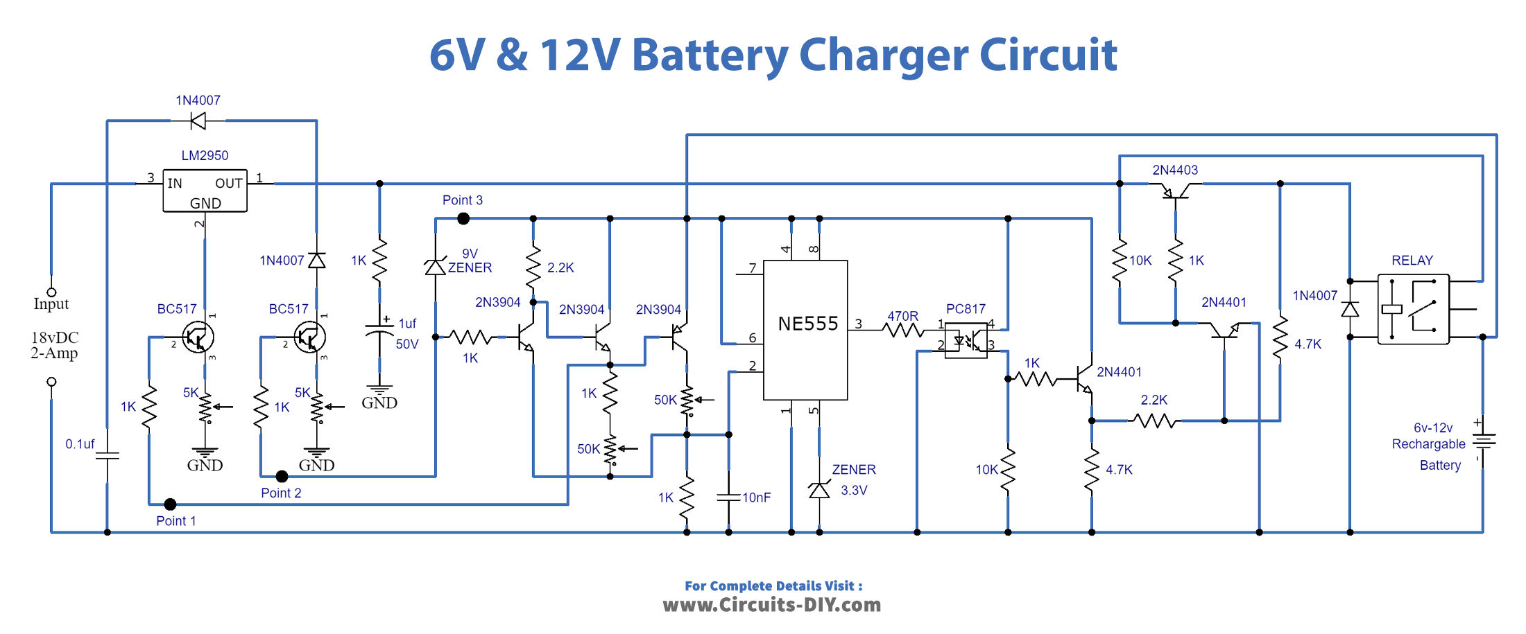
Working and Circuit Adjustments
After you are done building this circuit, there are some adjustments that need to be done before it’s working. In order to do that remove the battery from this circuit. Disconnect the 1K resistor from point one and connect it with the positive rail of the 18V power supply. Now connect this power supply with the circuit and connect a DMM at the output of the LM317 IC. Adjust the VR1 until the output voltage of the LM317 IC shows 7.5V. Now reconnect the 1K resistor to its original position i.e., point 1.
Repeat the same process with the 1K resistor at point 2, and adjust the VR2 until the LM317 shows 15V in the DMM. After this reconnect the 1K resistor to point 2. Remove the 18V power supply. Take another separate adjustable power supply and set its voltage to 7.2V. Connect it to point 3 (+) and ground/negative of the circuit. Slightly adjust the 50K pot1 and stop when the relay gets deactivated. Set 14.4V in the adjustable power supply and adjust pot2 again until the relay gets deactivated.
Now your circuit is ready to use and will perform working properly. Remove the adjustable power supply. Connect the 18V power supply with the circuit and connect the desired battery to charge.
Applications and Uses
It can be used to charge
- Lead Acid
- Sealed Lead Acid and other types of 6V or 12V batteries.