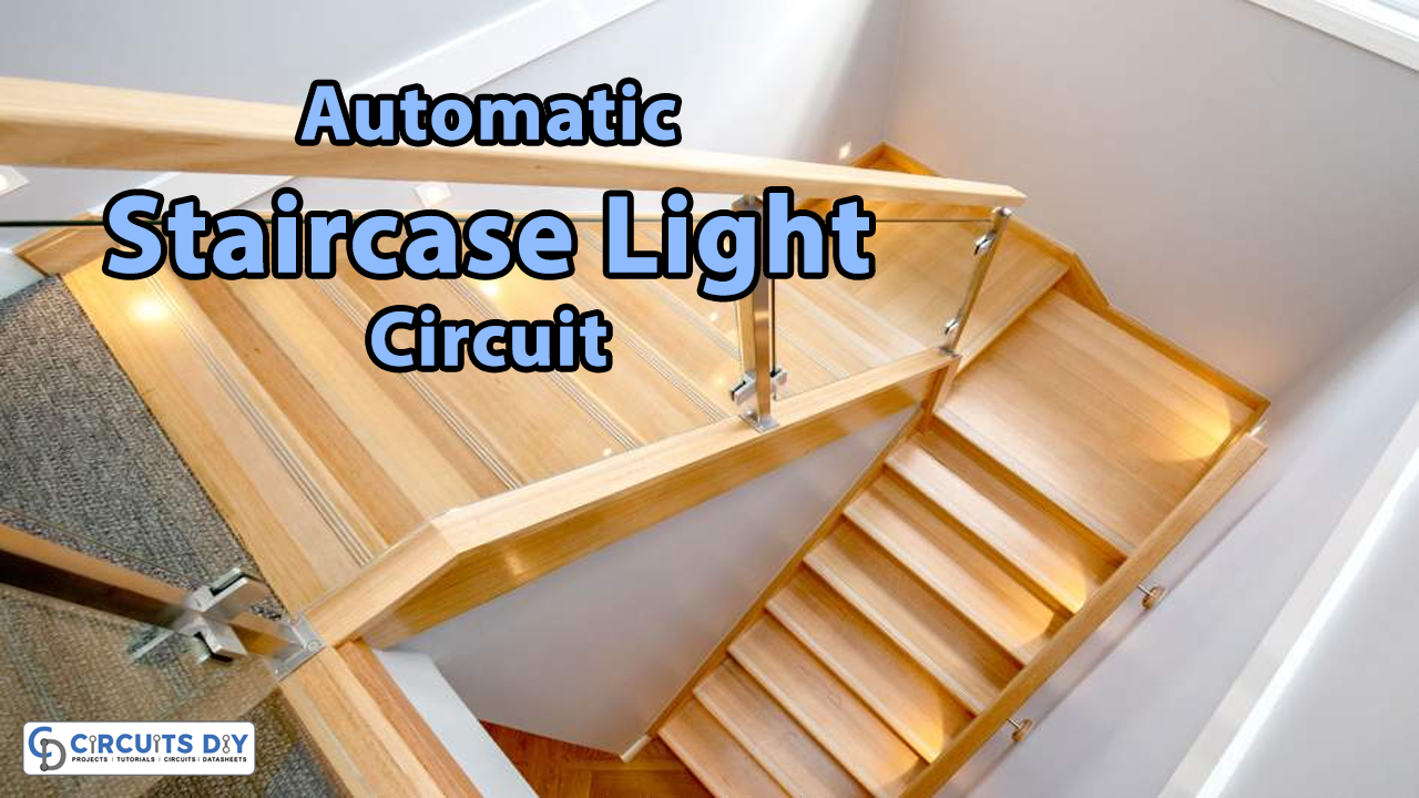
In this tutorial, we are going to make an “Automatic Staircase Light” using PIR. As we know that staircase lights are needed only when we walk through them, otherwise, we don’t need them. So we have to operate staircase lighting independently from common room lighting, to make each step safer. Smart staircase lighting transforms it into an elegant decorative fixture of the interior and makes the house more brightly lit and comfortable. The traditional way is using a two-way switch, to control the staircase light.
In which we manually turn ON/OFF the light, here is a simple and best solution to go automatic. Motion sensors with integrated light sensors are installed between the first and the last steps of the staircase. When crossing the coverage area of one of the sensors at night, the staircase lighting actuates automatically and sequentially illuminating each step-sensor.
PIR (Passive Infrared Sensor)
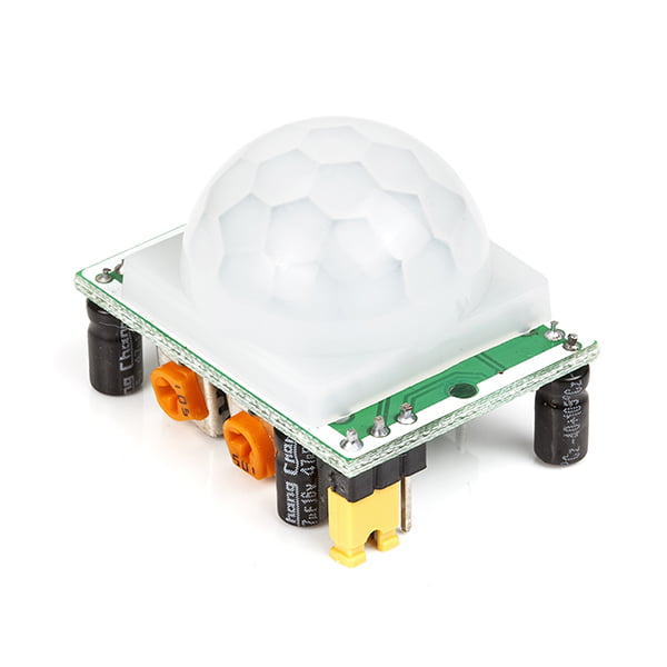
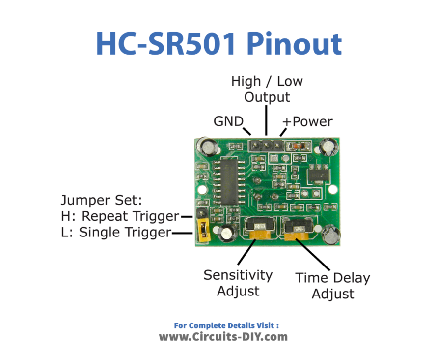
The PIR (Passive Infrared sensor) basically measures the infrared light radiated by an object present in its field. All living creatures (and objects) with a temperature above absolute zero (which is 0 Kelvin or -273oC), emit heat energy in form of radiation. The PIR sensors are tuned in such a way, that they detect only the radiation emitted by human beings. It detects the motion of a person and gives short-duration pulse output. With the help of this sensor, we can make the staircase light automatic. The PIR sensor HC-SR501 is easy to use and comes with three standard pins (Vcc, out, Gnd). Further, also it has onboard sensitivity adjustments and time delay adjustments. Hence we can get desired output from the PIR sensor. Here by using the Jumper setting, we can change the PIR sensor mode between H: Repeat trigger mode or L: Single trigger mode.
Hardware Required
| S.no | Component | Value | Qty |
|---|---|---|---|
| 1. | SPDT (Single Pole Double Throw) Relay | – | 1 |
| 2. | IC | LM7805 | 1 |
| 3. | PIR Sensor | HC-SR501 | 1 |
| 4. | Transistor | SL100 | 1 |
| 5. | Diode | 1N4007 | 5 |
| 6. | Transformer | – | 1 |
| 7. | Resistor | 1KΩ | 1 |
| 8. | Capacitor | 100uf,10uf | 1,1 |
| 9. | Connecting Wires | – | – |
| 10. | Bulb | – | 1 |
Circuit Diagram
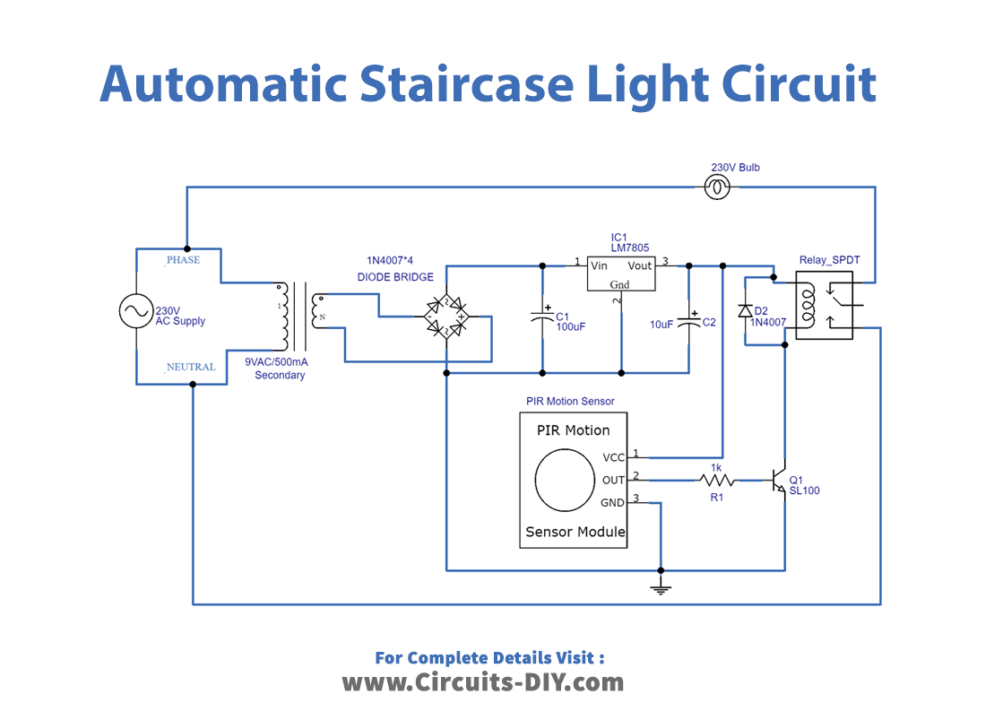
Working Explanation
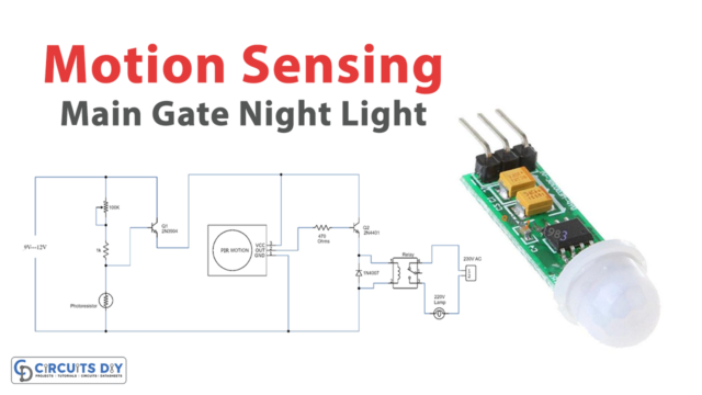
Here we have used simple and easily available components to construct the circuit. As we can see in the circuit, the PIR sensor HC-SR501 is connected with bias. And the output terminal is connected to the switching transistor SL100, through the R1 resistor. Then the SPDT (Single Pole Double Throw) relay coil is connected between Vcc and Q1 transistor’s collector. The bulb is connected between the phase line and relay N/O contact. Now the Pole terminal of the relay is connected to the neutral line of the AC supply. Here 230V AC primary to 9V AC 500mA secondary step-down transformer is used.
Now we powered the circuit, if the transistor is ON then the relay gets energized. Otherwise, the relay stays open. Here bridge rectifier and IC 7805 positive DC regulator are used to give bias to the whole circuit, it gives a constant 5V DC supply. The PIR sensor takes some duration to become stabilized. During that time output changes randomly for about 10 to 50 seconds, then becomes normal and starts to sense motion.
As we can see in this example prototype, fix the PIR sensor plastic cap facing toward the staircase steps. And then check the output & change the time delay, depending on the requirement of light duration then fix it. Now your staircase light becomes automatic.
Applications
Can be used in homes, malls, hospitals, and offices.