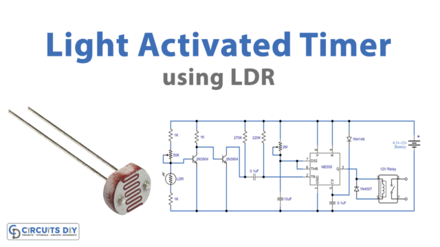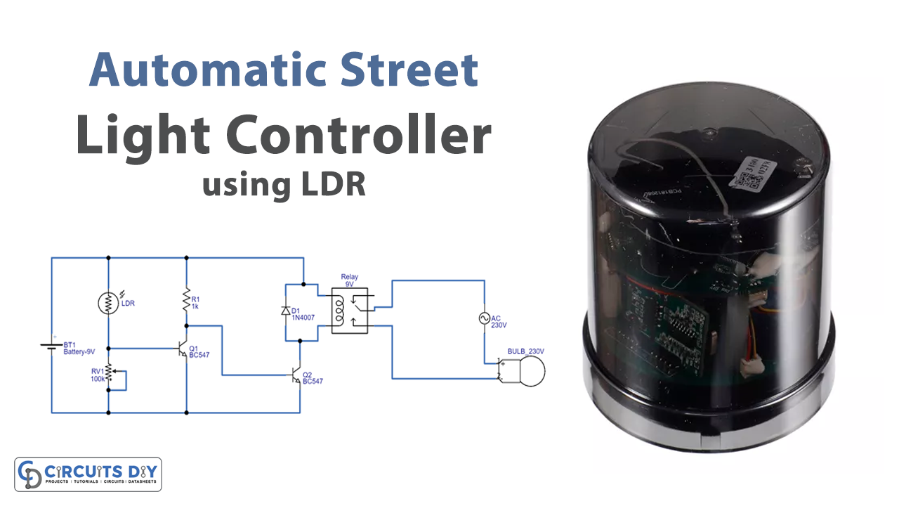
Introduction
To save energy and electricity you may have seen that many countries are adopting those electronic LED street lights which turn ON automatically after the sunset. Basically, these LED lights use LDR in their circuit. LDR, is a Light-dependent resistor, as the name implies resists the light. Hence, resistance increases as the light intensity got increases. At dark, the circuit starts working and that’s why suitable for street light circuitry. So, in this tutorial, we are going to ” Automatic Street Light Controller using LDR “. For the output, we are using a 230V bulb. In other words, you can say that circuit can easily operate an AC appliance of 230V.
Hardware Required
| S.no | Component | Value | Qty |
|---|---|---|---|
| 1. | LDR | 5mm | 1 |
| 2. | NPN Transistor | BC547 | 2 |
| 3. | Relay | 9V | 1 |
| 4. | Diode | 1N4007 | 1 |
| 5. | Potentiometer | 100KΩ | 1 |
| 6. | Electric Bulb | 230V | 1 |
| 7. | Resistor | 1KΩ | 1 |
| 8. | Battery | 9V | 2 |
Circuit Diagram
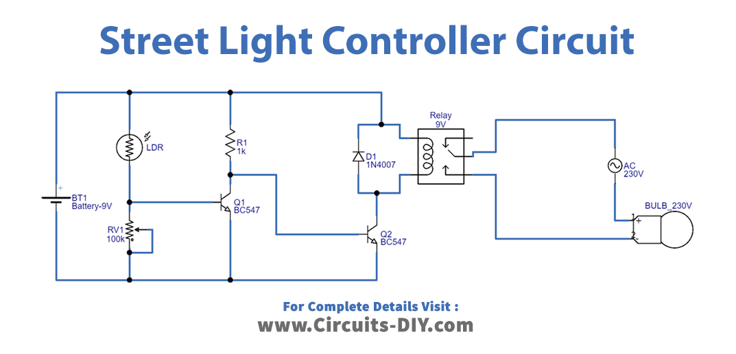
Working Explanation
In this circuit of Automatic Street Light Controller using LDR, when the light falls on LDR it becomes an element that is less resistive and therefore allows bias to appear at transistor Q1 base. It turns ON the transistor Q1. Since there is no bias at the base of transistor Q2, therefore it remains OFF. In this condition, the Relay coil is not getting the supply, hence remaining OFF. When no light falls on LDR, now it becomes a highly resistive element and there. In this case, no bias appears at the base of the Q1 transistor, so Q1 turns OFF, and bias arrives at the base of the transistor and turns ON the transistor Q2. Now the Relay coil gets power and therefore becomes energized and makes the contact. As a result output bulb starts to glow.
Application and Uses
- This circuit is mainly to make the street lights circuits.