Introduction
In this era, we have become more dependent on electronic devices and gadgets. From cell phones to headphones, it seems impossible for us t live without them. The way we can’t live without these gadgets, these gadgets cannot work without their batteries. And, batteries get drained and thus require the charger. The charger is of different kinds depending on the need of the device. But, sometimes we forget the device on charging, and energy gets wasted. Also, it can affect the battery life. Therefore, there should be a charger that immediately cuts off the charging when it gets charged. So, in this tutorial, we are going to “Battery charger circuit diagram with auto cut-off”.
You may have seen that in some devices when we charge a gadget and it becomes full, it instantly cuts off all incoming signals. These are the chargers that constantly check the battery’s charging voltage and turn off the charging voltage when the battery is fully charged.
Hardware Required
| S.no | Component | Value | Qty |
|---|---|---|---|
| 1. | Transformer | 0-16V | 1 |
| 2. | Diode | 1N4007 | 5 |
| 3. | Battery | 12V | 1 |
| 4. | Zener Diode | 12v/1w | 1 |
| 5. | Voltage Regulator IC | LM317 | 1 |
| 6. | NPN Power Transistor | BD139 | 1 |
| 7. | LED | 2 | |
| 8. | Potentiometer | 10K | 1 |
| 9. | Electrolysis Capacitor | 1000uf | 1 |
| 10. | Ceramic Capacitor | 0.1uf | 1 |
| 11. | Resistor | 1K, 2K, 10 Ohm, 230 Ohm | 1, 1, 1, 1 |
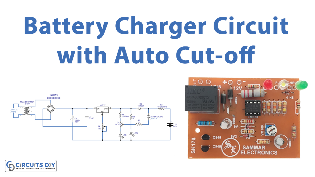
Circuit Diagram
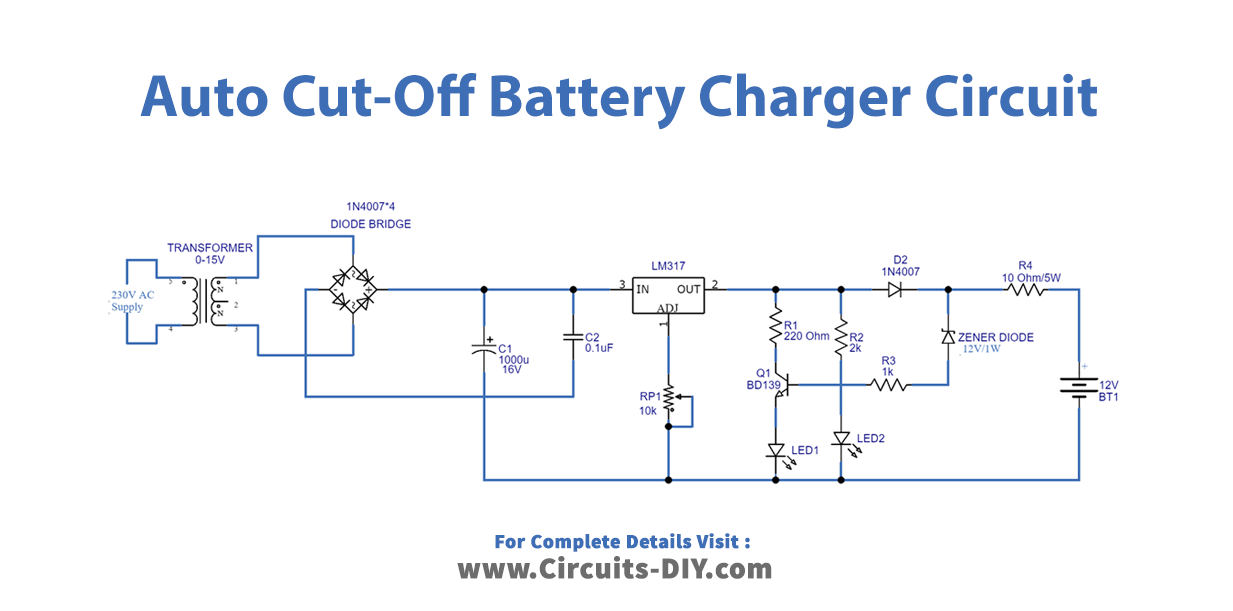
Working Explanation
The Battery charger circuit diagram with auto cut-off includes a transformer that reduces the voltage from 230V to 15V. Then, using diodes, we built a bridge rectifier that converts AC power to DC, but it has ripples that are removed by the capacitors in the circuit. This output is now used as an input to the LM317 regulator IC, which regulates DC voltage. As a result, it adjusts the voltage via a potentiometer on its adjust pin. The circuit now has a transistor and a Zener diode.
When the battery is fully charged, reverse voltage is applied to the base of the transistor BD139 through a Zener diode, causing it to turn on due to conduction in the transistor. When the battery is fully charged, the voltage regulator’s output voltage is reduced. We utilized two different colored LEDs. The green LED indicates that the battery is charging, and the red LED indicates that the battery has reached its full charge.
Application and Uses
- One of the most common applications of a 12-volt battery is for electronic gadgets and equipment.