The CD4514BC and CD4515BC are 4-to-16 line decoders with latched inputs implemented with CMOS circuits constructed with N- and P-channel enhancement mode transistors. CD4515 presents a logical “0” at the selected output. The input latches are R–S type flip-flops, which hold the last input data presented prior to the strobe transition from “1” to “0”. The CD4515 offers a wide array of features such as ESD protection, thermal overload protection, and a wide array of workable voltages. The IC is very simple to use and is easily interfaceable with CMOS, NMOS, and TTL

What is a Latch Circuit?
A latch is a device that can be used to store one bit of information. The latch is used to capture, or ‘latch’ the logic level which is present on the Data line when the clock input is high. For example, in the case of a d-type latch, If the data on the D line changes state while the clock pulse is high, then the output, Q, follows the input, D. When the CLK input falls to logic 0, the last state of the D input is trapped and held in the latch.
CD4515 Key Features
- ide supply voltage range: 3.0V to 15V
- High noise immunity: 0.45 VDD (typ.)
- Low power TTL: fan out of 2
- compatibility: driving 74L
- Low quiescent power dissipation:
- 0.025 µW/package @ 5.0 VDC
- Single supply operation
- Input impedance = 1012Ω typically
- Plug-in replacement for MC14514, MC14515
CD4515 Pinout
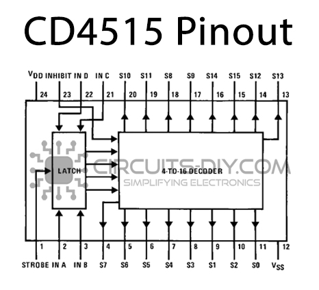
| Pin No | Pin Name | Description |
|---|---|---|
| 1 | STROBE | Strobe Pin |
| 2 | IN A | Input A of Line Decoder |
| 3 | IN B | Input B of Line Decoder |
| 4 | S7 | Output 7 of Line Decoder |
| 5 | S6 | Output 6 of Line Decoder |
| 6 | S5 | Output 5 of Line Decoder |
| 7 | S4 | Output 4 of Line Decoder |
| 8 | S3 | Output 3 of Line Decoder |
| 9 | S1 | Output 1 of Line Decoder |
| 10 | S2 | Output 2 of Line Decoder |
| 11 | S0 | Output 0 of Line Decoder |
| 12 | VSS | Source Supply |
| 13 | S13 | Output 13 of Line Decoder |
| 14 | S12 | Output 12 of Line Decoder |
| 15 | S15 | Output 15 of Line Decoder |
| 16 | S14 | Output 14 of Line Decoder |
| 17 | S9 | Output 9 of Line Decoder |
| 18 | S8 | Output 8 of Line Decoder |
| 19 | S11 | Output 11 of Line Decoder |
| 20 | S10 | Output 10 of Line Decoder |
| 21 | IN C | Input C of Line Decoder |
| 22 | IN D | Input D of Line Decoder |
| 23 | INHIBIT | Inhibit Pin |
| 24 | VDD | Drain Supply |
Application
- Digital Multiplexing
- Address Decoding
- Hexadecimal/BCD Decoding
- Program-counter Decoding
- Control Decoder
CD4515 Datasheet
You can download the datasheet for CD4515 4-bit Latch IC from the link given below:
See Also: 74LS08 Quadruple Two Input AND Gate IC |74LS32 Quad 2 – Input OR Logic Gate IC| 74LS25 Dual 4 – Input NOR Gate IC with Strobe