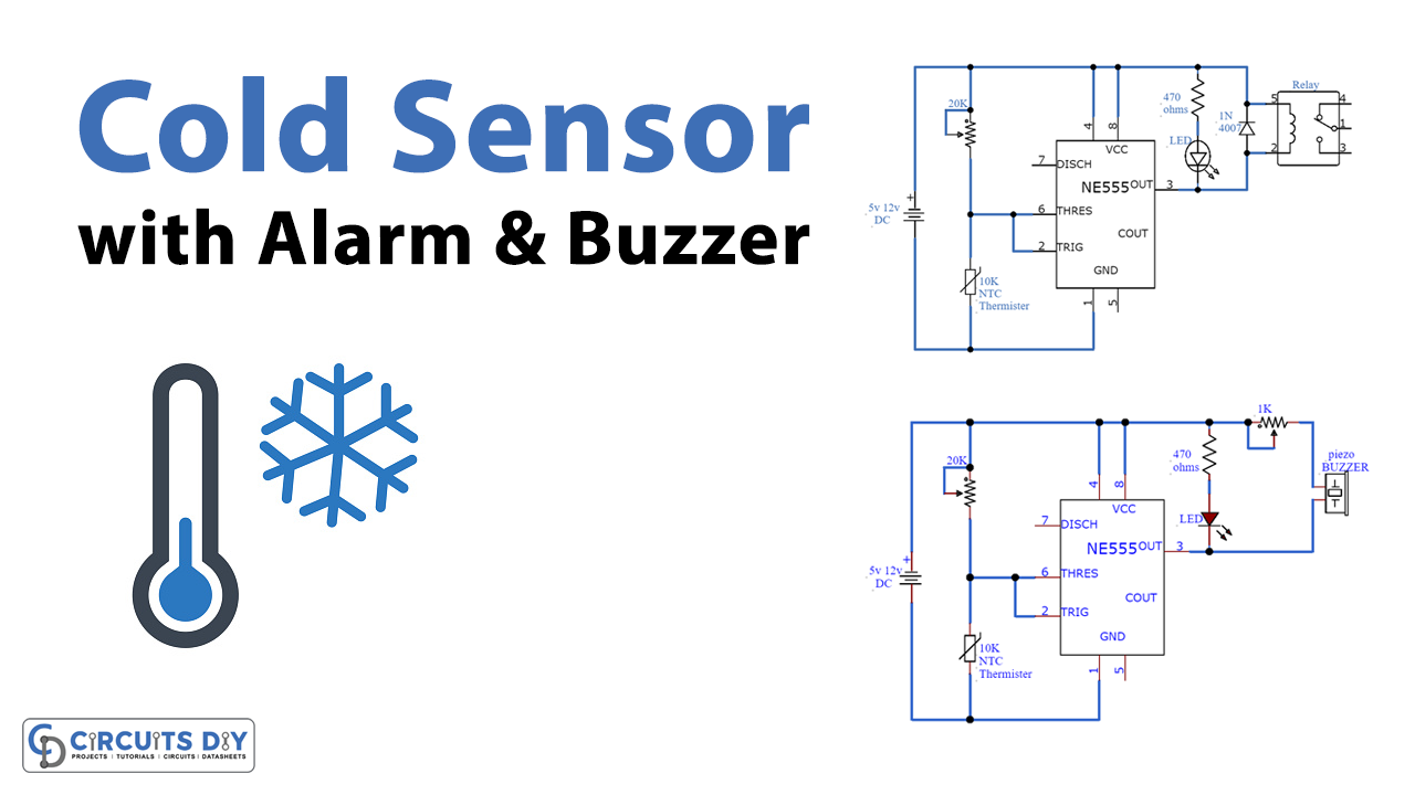
In this tutorial, we are making a cold sensor alarm in the simplest way possible. We are using a 555 timer IC here, you must be familiar with this IC because it is used in most of the circuits. It’s inexpensive and doesn’t need many components and gets the job done accurately.
There are two circuit diagrams both are doing the same things only the output is different so that you can have both options. If you want to operate an appliance then built the circuit using relay and LED, if you just want to be notified and the alarm is enough for you then use the circuit with a buzzer.

Hardware Components
The following components are required to make Cold Sensor Alarm Circuit
| S.no | Component | Value | Qty |
|---|---|---|---|
| 1. | Input Supply DC | 5-12V | 1 |
| 2. | Thermistor | 10KΩ | 1 |
| 3. | LED | – | 1 |
| 4. | Variable Resistor | 20K, 1K | 1 |
| 5. | Resistor | 470Ω | 1 |
| 6. | Piezo buzzer | – | 1 |
| 7. | IC | NE555 Timer | 1 |
| 8. | Diode | 1N4007 | 1 |
| 9. | Relay | – | 1 |
NE555 IC Pinout

For a detailed description of pinout, dimension features, and specifications download the datasheet of 555 Timer
Cold Sensor Alarm Circuit


Working Explanation
The operating voltage if this circuit is 5 to 12 volts DC. We are using NTC thermistors as a cold sensor. When the temperature drops from the preset level set by the circuit, the thermistor’s resistance will decrease and it will activate the 555 timer IC. The IC will send a high output which activates LED and a relay switch or a buzzer (depending on your preference) till the temperature rises from that level. You can also experiment with thermistors or variable resistor values. The level of temperature at which you want to activate the circuit is adjusted by a 20K variable resistor.
Applications and Uses
- Temperature sensor device
- Heaters
- Bulbs
- Industrial and laboratory applications