
Introduction
In numerous electrical circuits, no voltage regulators are available there, henceforth assuming there is any adjustment of the input voltage, it would be reflected or show up on the output side too. We mostly used these kinds of circuits for LED lights, DC engines, and so forth.
In this way, we can say that unregulated voltage permits the variation on the output side. However, for, any electronic appliances like PCs, TVs, and so forth, these varieties can be harmful because they can cause temperature variation, so to beat this, the circuits called voltage regulators are utilized. It diminishes the fluctuations and ripples in the voltages. Consequently, to see all of this, in this tutorial, we are going to “LP2950 Adjustable Micropower Voltage Regulator Circuit”
Hardware Components
The following components are required to make an Adjustable Voltage Regulator Circuit
| S.no | Component | Value | Qty |
|---|---|---|---|
| 1. | IC | LP2950 | 1 |
| 2. | Variable Resistor | 1K | 1 |
| 3. | LED | – | 1 |
| 4. | Electrolytic Capacitor | 1µF | 2 |
| 5. | Resistor | 220Ω, 100Ω | 1, 1 |
| 6. | 2 Pin Connector | 2 |
LP2950 Pinout
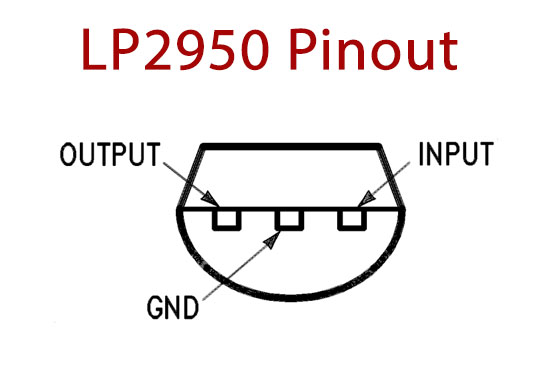
For a detailed description of pinout, dimension features, and specifications download the datasheet of LP2950
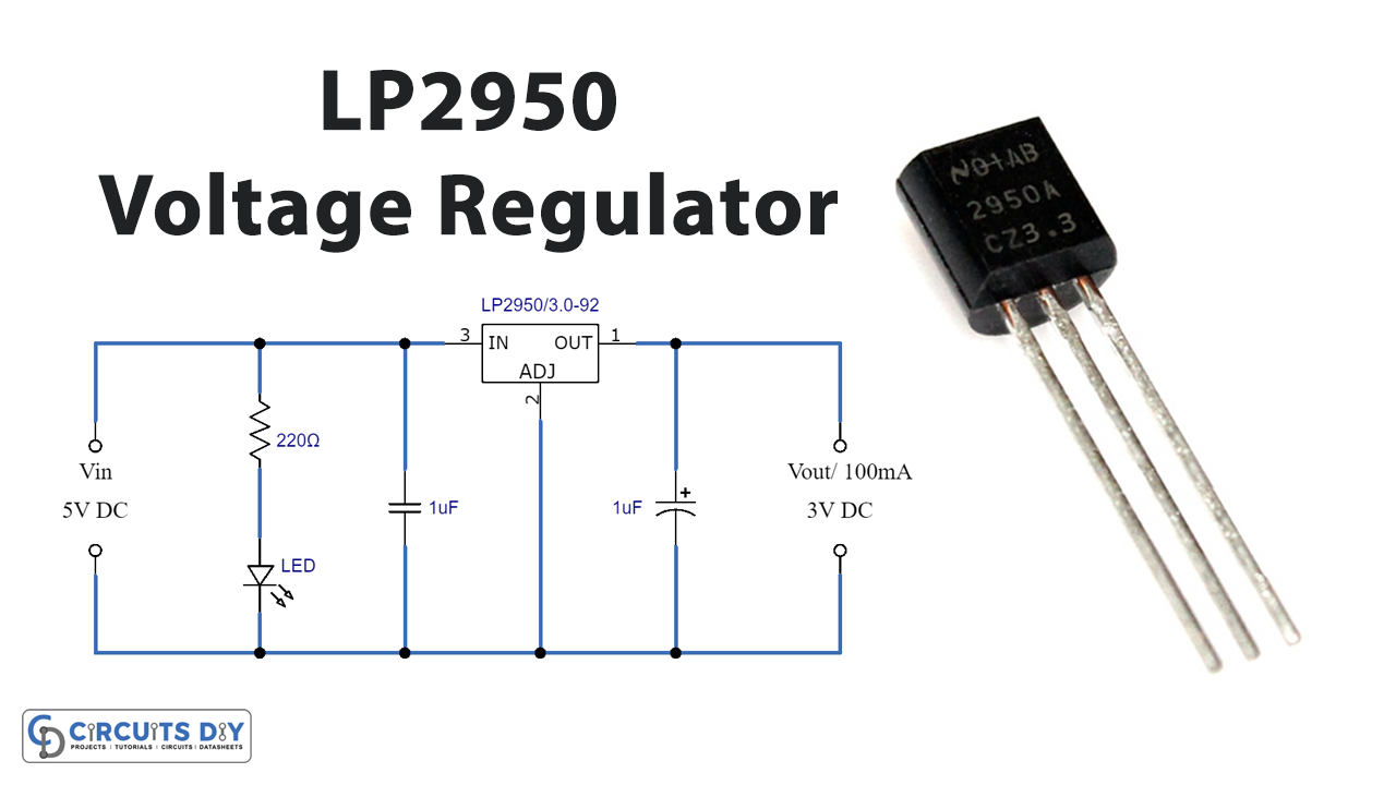
Adjustable Voltage Regulator Circuit
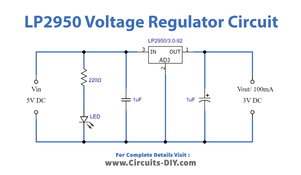
Working Explanation
There are two Voltage Regulator Circuits here in this article. For Fixed Regulator capacitors C1 and C2 work as a filter, where LED shows input voltage presence. For Adjustable Regulator Ground pin of LP2950 is associated with the Voltage divider Resistor arrangement, here the RV1 potentiometer is a Variable one and R2 is a Fixed one, By adjusting the value of the RV1 Resistor we can Control the ground supply to the GND pin of LP2950 and we can change the output voltage.
Application and Uses
- Power supplies.
- Different electronic devices, circuits, and gadgets.
Related posts:
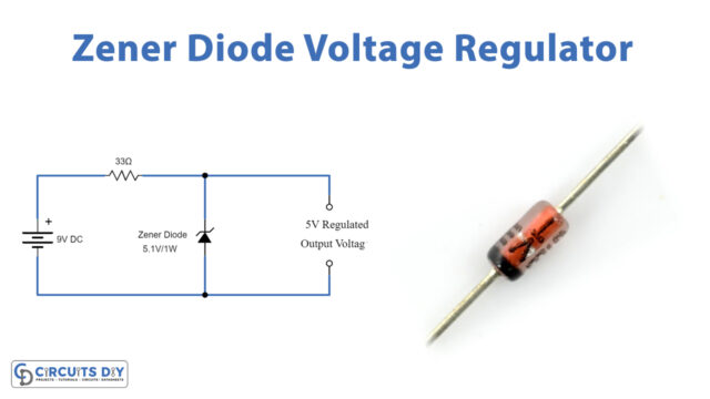 Zener Diode Voltage Regulator Circuit
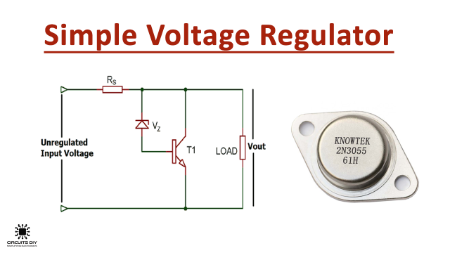 Simple Voltage Regulator using 2N3055 Transistor
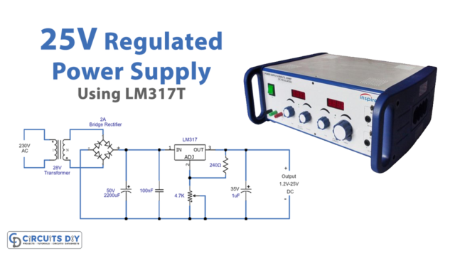 25V Regulated Power Supply Using LM317T Voltage Regulator
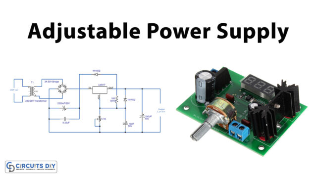 Adjustable Power Supply Circuit using LM317 Voltage Regulator IC
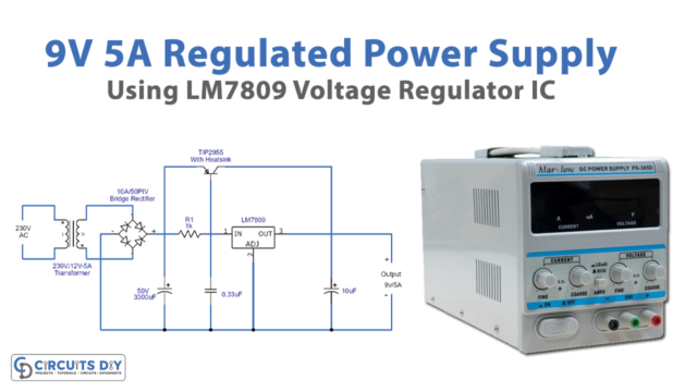 9V/5A Regulated Power Supply Using LM7809 Voltage Regulator
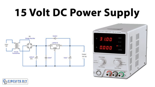 15V DC Power Supply Circuit Using LM7815 IC


