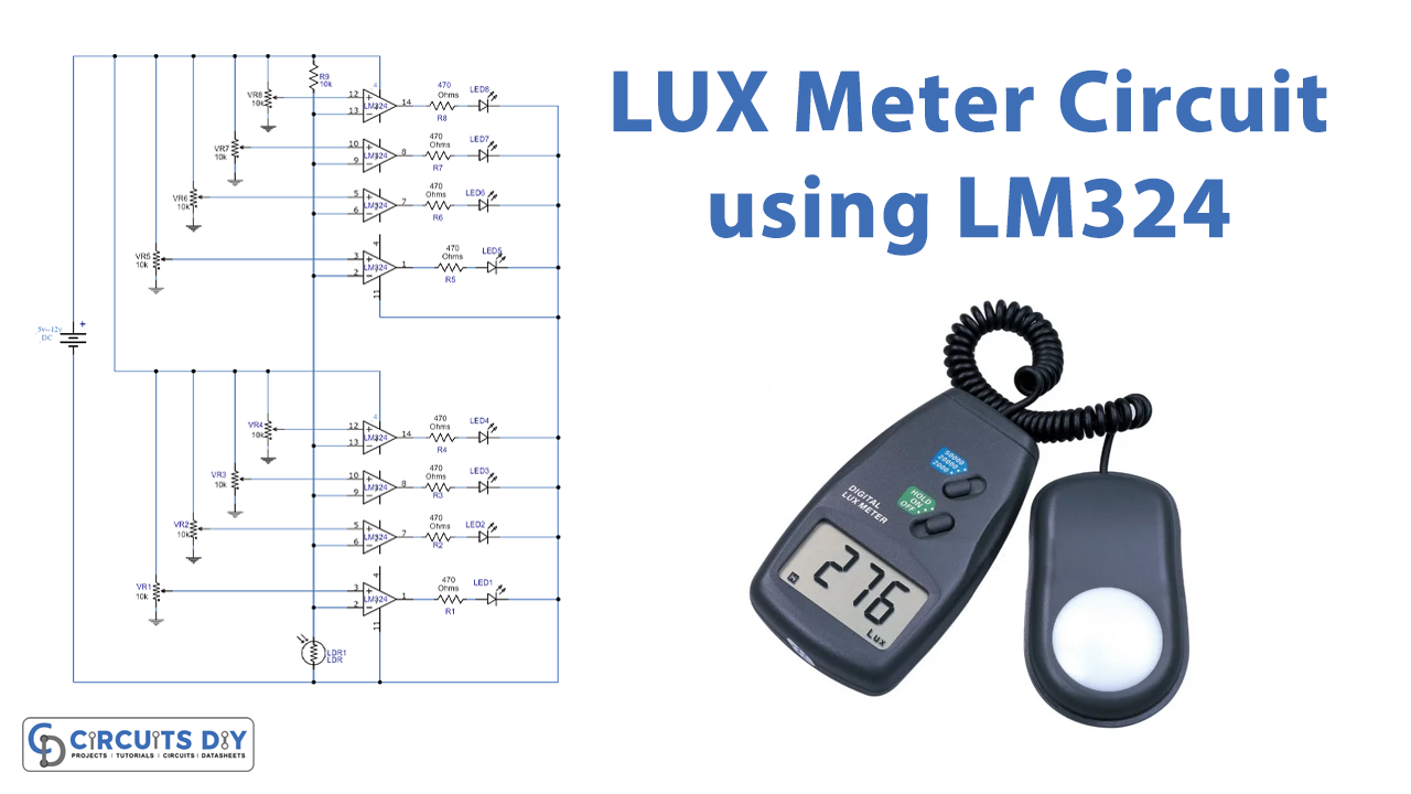
A LUX meter detects and distinguishes between the different intensities of light. For this purpose, the circuit uses two LM324 ICs and a few discrete components. Also, the circuit represents the different light intensities through LEDs.
Hardware Required
| S.no | Component | Value | Qty |
|---|---|---|---|
| 1. | DC Battery | 5V-12V | 1 |
| 2. | LDR | – | 1 |
| 3. | IC | LM324 | 2 |
| 4. | Variable Resistor | 10K | 8 |
| 5. | Resistor | 470Ω, 10K | 8, 1 |
| 6. | LEDs | – | 8 |
Circuit Diagram
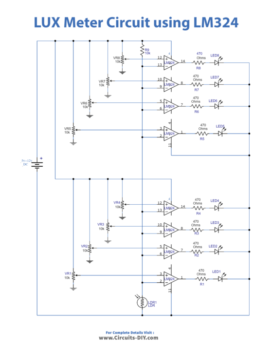
Circuit Explanation
IC LM324 has built-in four independent operational amplifiers. Moreover, this circuit involves the functioning of all four op-amps of both ICs. Also, four 10KΩ variable resistors are attached to each of the IC’s PINs 3, 5, 10 & 12. Thus, different levels of light intensity values are set by setting up the potentiometer.
Firstly, the light is detected and an electrical signal is generated. After that, both the ICs input PINs 2, 6, 9, and 13 receive this signal. Secondly, each op-amp in the IC compares the electrical signal with the preset value of the potentiometer. Thus, the relative output is given out by the ICs through their output PIN 1, 7, 8 & 17. At last, the LEDs corresponding to the IC’s output PIN light up.
The resistor of 470Ω acts as a current-limiting resistor for LEDs. Furthermore, for operating the circuit under 9V, replace the current limiting resistor value to 270Ω or 330Ω.
Application
- Different light bulb intensity meter.
- In electronics LAB testing for light intensities