In this tutorial, we will make a “Mobile Phone Detector Circuit”.
A mobile phone detector device can identify the existence of an activated cell phone nearby and give an indication of an activated cell phone near it. The cell phone detector is a frequency detector or a current to voltage converter device, which detects frequencies between 0.8 and 3.0 GHz (Mobile Band Frequencies). Here we can locate active mobile by detecting its electromagnetic signal. We know that every mobile phone operates under 800 MHz to 2100 MHz range of frequency spectrum, mobile phone detector circuit detects only electromagnetic signals caused by active mobile phones, and switched off mobiles can’t be located. We design a simple portable phone detector circuit with a few easily available components and we can detect any kind of active mobile phone within a room or specific space.
Hardware Components
The following components are required to make Mobile Phone Detector Circuit
| S.no | Component | Value | Qty |
|---|---|---|---|
| 1. | IC | LM358 | 1 |
| 2. | Transistor | BC548 | 1 |
| 3. | Variable Resistor | 1MΩ | 1 |
| 4. | Resistor | 100KΩ,220KΩ,1KΩ | 1,1,1 |
| 5. | Electrolyte Capacitor | 1µF, 100µF | 2, 1 |
| 6. | Aerial Antenna | – | 1 |
| 7. | Buzzer | – | 1 |
| 8. | LED | – | 1 |
| 9. | Connecting Wires | – | – |
| 10. | Battery | 5V | 1 |
LM358 Pinout

For a detailed description of pinout, dimension features, and specifications download the datasheet of LM358
Mobile Phone Detector Circuit
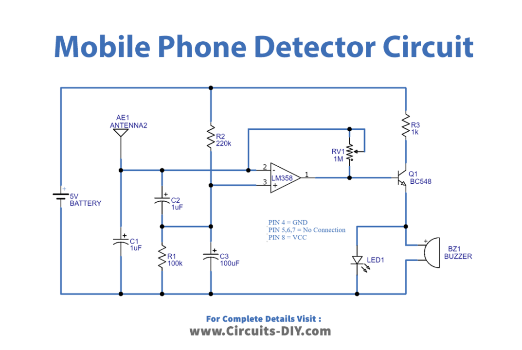
Working Explanation
As we can see that the circuit has three stages first is the electromagnetic pickup stage second is the amplification stage and then the output alert stage. The circuit is based on an op-amp with some active-passive components. Op-amp is configured as a frequency detector, so the first thing we need to place is a low-power dual operational amplifier IC LM358 with proper bias. We need only one operational amplifier from IC LM358 and left the other open. Antenna to be connected to the Inverting input with variable resistor RV1 feedback path. Non-inverting input pin placed between R2 and C3 capacitor. Output from the operational amplifier connected to the base terminal of the Q1 transistor and, LED are connected at the emitter pin. buzzer and LED are used for an indication of the presence of a cellphone.
When a mobile phone is active, it radiates RF signals in the form of electromagnetic radiation, the antenna detects it and converts it into a very low-power electric signal, capacitor C3 absorbs it and uses it as an input to LM358 IC. Then this signal gets amplified by the LM358 operational amplifier, and the output of LM358 is connected to LED via transistor which gets turned ON. Then the flashing of the LED is observed. Here buzzer and LED indicate the hidden mobiles through sound and blink. This is how, it can identify the mobile phone RF transmission and triggers Buzzer to produce a beep sound, even though the phone has stayed in Silent mode and this alert system continues to beep until RF signals are present. The potentiometer RV1 is used to adjust the sensitivity or range of the circuit.
Applications
This prototype circuit will be useful for the mobile restricted area and mobile detecting applications.