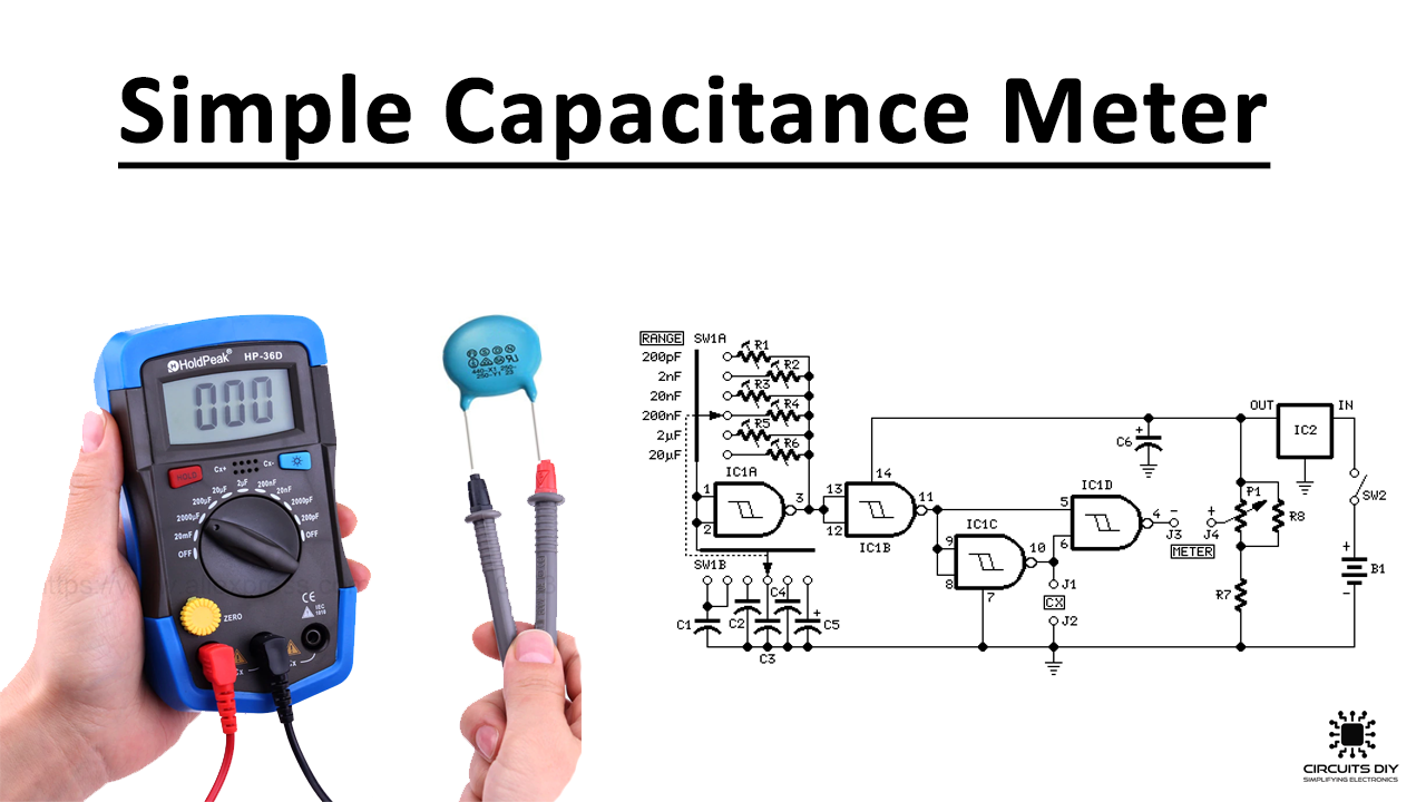
In this tutorial, we are going to make a capacitance meter. It is mainly used to measure the value of capacitors obtained after dismantling electronic appliances. You can find a good quality capacitor but their values are unknown because the lettering on the case is usually hard to read and sometimes completely erased. This circuit can measure capacitors ranging from 1pF to 22µF with good accuracy.
If you are using low tolerance capacitors for C1-C5, it will be even more appealing because it requires a common analog/digital multimeter. It will be set to 2V DC voltage range to clearly display the unknown value of the capacitor. This circuit will give a direct reading of the capacitor in conjunction with a voltmeter.
Hardware Components
| S.no | Component | Value | Qty |
|---|---|---|---|
| 1. | Potentiometer | 470R | 1 |
| 2. | Resistor | 10K 1/4W, 47KR 1/2W, 100R 1/4W | 1, 6, 1 |
| 3. | Polyester Capacitor C1 | 1nF/63V, 10nF/63V, 100nF/63V, 1µF/63V, 10µF/25V, 10µF/25V, 47µF/25V | 1, 1, 1, 1, 1, 1 |
| 4. | Schmitt NAND Gate IC | 4093 | 1 |
| 5. | Voltage Regulator IC | 78L05 | 1 |
| 6. | Switch S1 | 6 ways Rotary | 1 |
| 7. | Switch S2 | Toggle or Slide | 1 |
| 8. | Chassis Sockets | 1 or 2mm | 2 |
| 9. | Output sockets | 4mm | 2 |
| 10. | Battery | 9V | 1 |
| 11. | Clip for PP3 Battery | – | 1 |
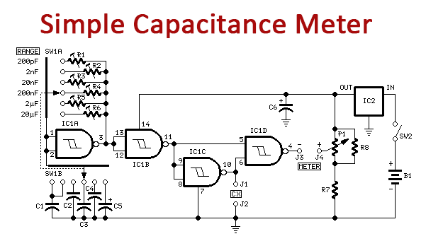
Circuit Diagram
Working Explanation
IC1A and IC1B are working as an oscillator and buffer. The frequency of these ICs is set by variable resistors R1-R6 and capacitors C1-C5. Two switches are used SW1A and SW1B to switch this circuit in 6 different ranges. The output coming from this will go to IC1D, one of its inputs is inverted and delayed by the unknown component by a time proportional to its value.
Its output is normally high, a negative pulse with a width proportional to the capacitance appears. The duty cycle of the output and the average voltage indicates the value of capacitance at the meter. For accuracy the voltage supply should be stable therefore we are using another IC which is a 5V Voltage regulator IC.
Circuit Calibration:
To calibrate the circuit set the DVM to its 2V range and remove capacitor Cx. Adjust P1 to give a zero reading (a very narrow pulse will be shown at this point due to the inherent delay of IC1C). For ranges, 2 to 6 connect a capacitor of same value and tolerance of C2 to C5 in the position of Cx. Adjust the variable resistors and set the frequency switch to reading the correct value on the meter display.
This should be repeated five times by connecting each capacitor at the Cx position and adjusting the variable resistor accordingly. For calibrating the first range for the capacitor 200pF, set the frequency switch in the first position and connect a 100pF capacitor as Cx. Now adjust R1 for a reading of 100 on the meter display.