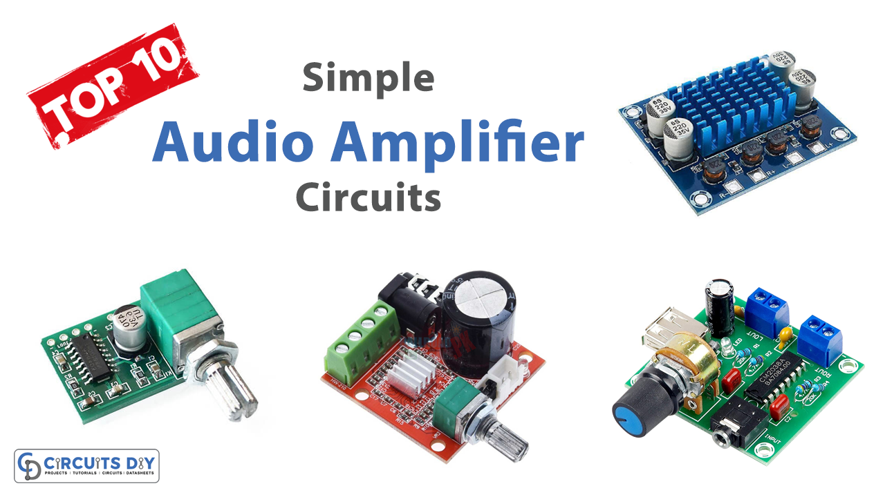
Introduction
In some previous articles, we have already discussed that amplifiers are signals that increase the voltage or power. Audio amplifiers, therefore, transform extremely low audio signals into higher ones. Thus, in this article, we are discussing the Top 10 Simple Audio Amplifier Circuit
Top 10 Simple Audio Amplifier
1. Simple Basic Audio Amplifier
Circuit Diagram
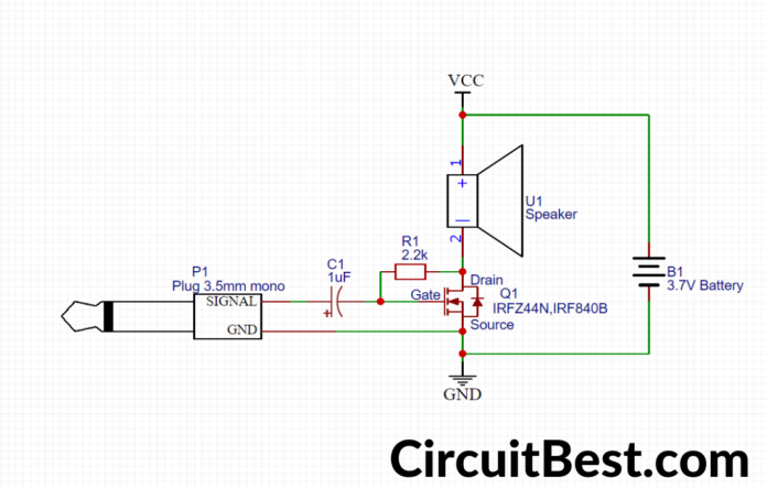
Working Explanation
Connect the Simple Basic audio Amplifier according to the diagram attached to this article. Remember that the adapter wire has three wires, and we need only two wires, so use the ground one for the ground and any other wire as a signal wire. After the proper connections, provide the power supply to the circuit. Now, connect the adapter to your mobile phone and play audio. The signal coming from the headphone jack adapter triggers the base of an N channel MOSFET, wired in the circuit. This N-channel MOSFET amplifies the input signal. Thus, the drain of the Mosfet drives the speaker at the load.
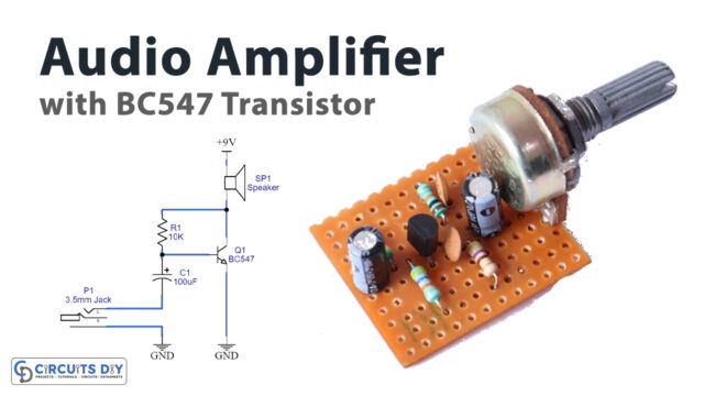
2. Simple Basic Audio amplifier with BC547 Transistor
Circuit Diagram
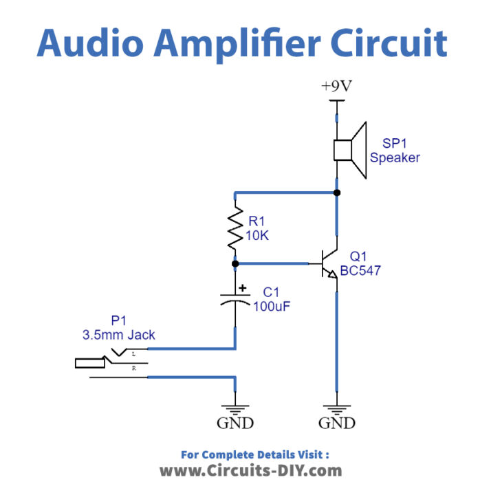
Working Explanation
This simple basic audio amplifier circuit first receives a low input audio input signal of any kind with the help of a 3.5mm Jack. This audio signal is then given to the base of the transistor through the 100uf capacitor. The capacitor triggers the NPN transistor therefore the transistor starts operating. The transistor magnifies the audio signal. The transistor is wired in a common emitter configuration. Therefore emitter is grounded and output is taken at the collector. Hence, the speaker is connected to the collector. A high-output audio signal is observed at the output. A resistor is there to manage the sound quality at the output.
3. Audio Amplifier-Low-Power
Circuit Diagram
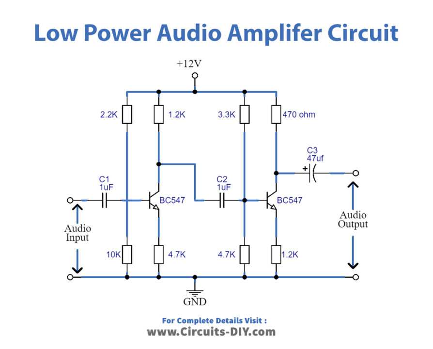
Working Explanation
This Audio Amplifier-Low-power uses the two BC547 transistors. Since we know that amplifiers do not change the shape or frequency it is necessary to use two transistors. Both the transistors are working in the same way. The first amplifier amplifies the signal and provides 180 degrees of the phase shift. As we need no phase shift, that’s why the second transistor does another phase shift of 180 degrees? Consequently, we get the phase shift of 360 degrees, which is 0 degrees in general. hence, we get the amplified output signal with zero phase shift.
4. Simple Class D Amplifier Schematic
Circuit Diagram
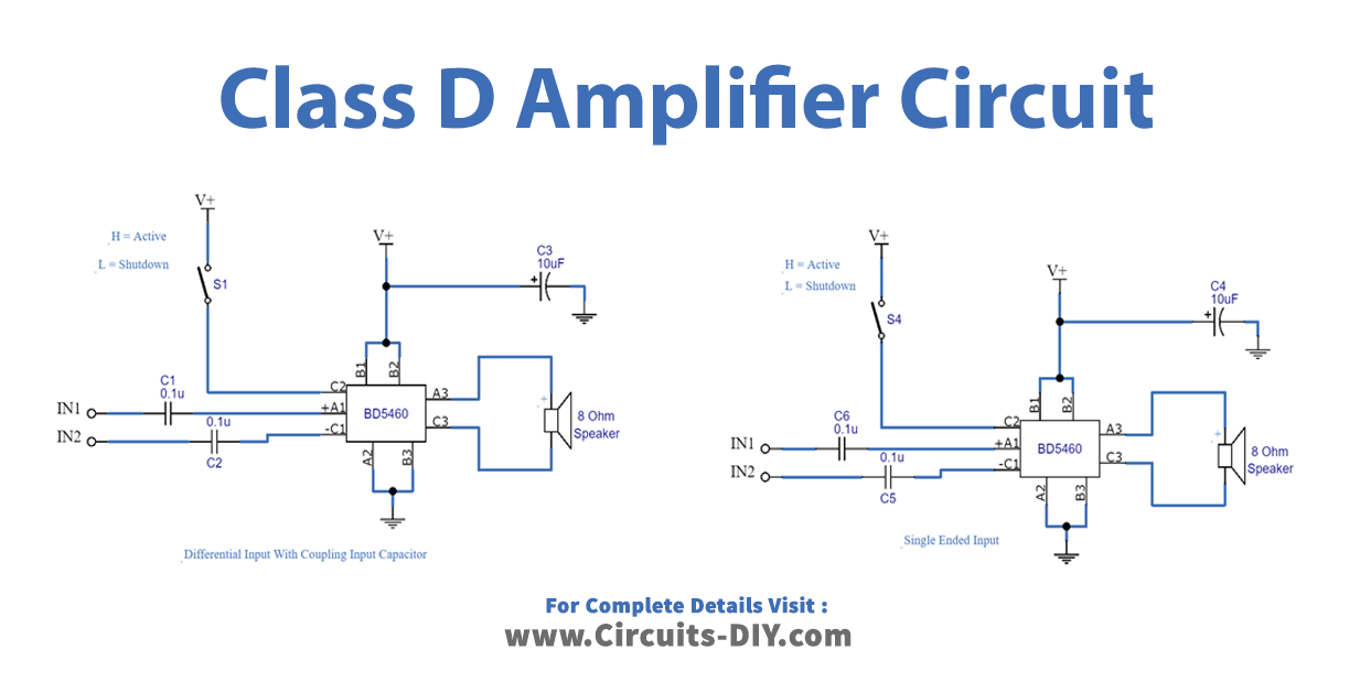
Working Explanation
In this Simple circuit, we are using two BD5460. The first one works as a differential input class D amplifier. On the other side, the second one is a single-ended input class D amplifier. There are four input DC decoupling capacitors: C1, C2, C3, and C4. The lower cut-off frequency is depending on these capacitors. The capacitors C5 and C6 are the power supply filter capacitor. There are two shutdown switches S1 and S2. When we connect the C1 pin to the high logic, the IC gets activated and when you connect the C1 pin to the ground pin, the IC will go into shutdown mode.
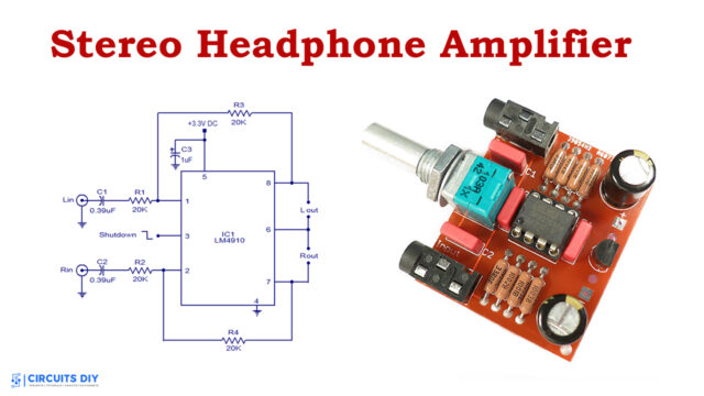
5. Stereo Audio Amplifier using PAM8403
Circuit Diagram
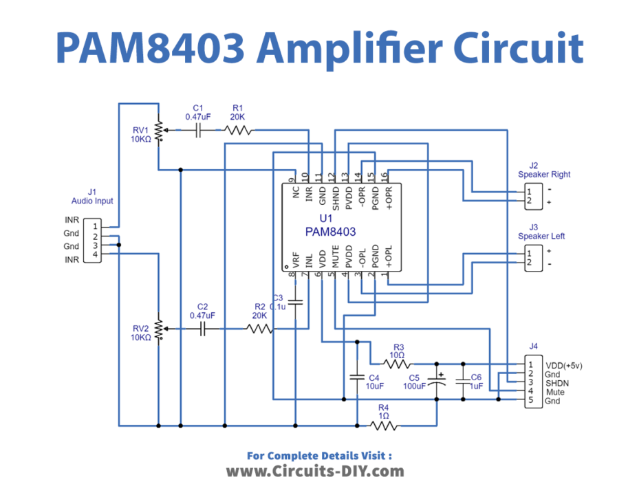
Working Explanation
Connect the Simple PAM8403 Amplifier Circuit according to the diagram given above. The IC has 16 pins. The IC has two channels. Pin 7 is the left channel input. The output of that channel is taken at pins 1 and 3, pin 1 is the positive output, and pin 3 provides the negative output for the left channel. Similarly, pin 10 is the right channel input. , Output of that channel is taken at pins 14 and 16, pin 16 is the positive output, and pin 14 provides the negative output for the left channel. At input channels, there are potentiometers to adjust the audio.
6. Simple Amplifier Circuit without IC
Circuit Diagram
Working Explanation
This simple amplifier circuit first takes a low input audio input signal of any kind. The audio signal is then transferred to the base of the transistor. This triggers the transistor so transistor stats work. This NPN transistor amplifies the audio signal. The transistor is wired in a common emitter configuration. Therefore emitter is grounded and output is taken at the collector. Hence, the speaker is connected to the collector. A high-output audio signal is observed at the output. A resistor is there to manage the sound quality at the output.
7. TDA2030 Audio Amplifier 15W Circuit
Circuit Diagram
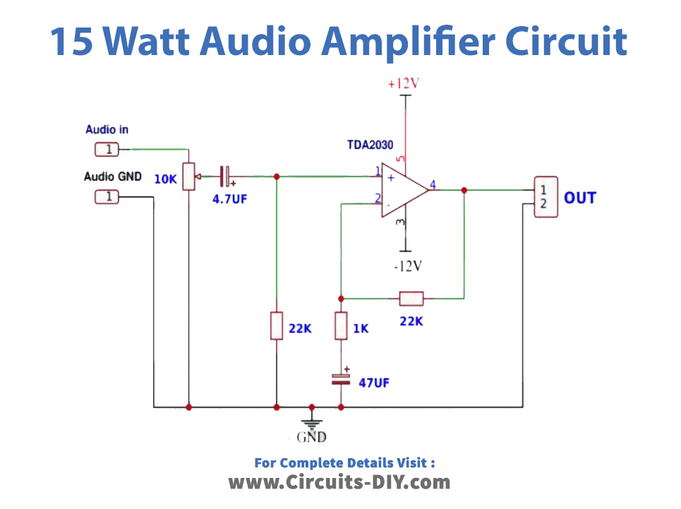
Working Explanation
In this TDA2030 Audio Amplifier 15W Circuit, we are using an AC supply and that’s why we first need the power supply circuit. So in this case, the circuit is divided into two parts.
In the first part, there is a transformer that steps down the 220V AC. Then we made the rectifier circuit to convert AC into DC, which may have ripples that are filtered by the capacitor. There is an LED in the circuit that turns ON when getting the DC supply.
This DC supply is now given to turn ON the main circuit, we then provide the input audio signal to the circuit. The circuit is effectively blocking the DC component of the input signal using a coupling capacitor, letting only AC pass through. The amplifier’s amplified output is subsequently delivered to an audio transducer like a loudspeaker.
8. Audio Amplifier Circuit using TDA2030 IC
Circuit Diagram
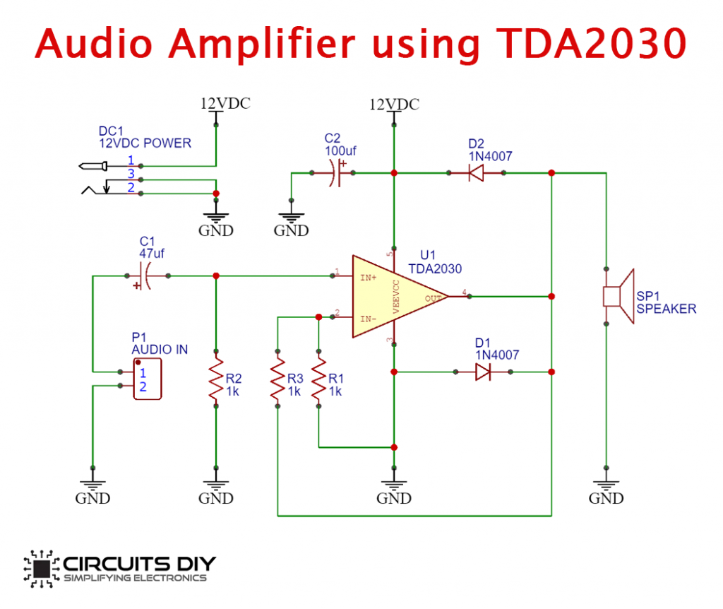
Working Explanation
The operation of this Audio Amplifier Circuit using TDA2030 IC is quite simple. First, we are providing a 12V DC supply. You can use 6V to operate this circuit an audio input device, such as a smartphone or a microphone, is used. It then passed the audio input through a 47uF coupling capacitor.
The circuit is effectively blocking the DC component of the input signal using a coupling capacitor, letting only AC pass through. We then wired the capacitor output to the IC’s non-inverting input pin.
The amplifier’s amplified output is subsequently delivered to an audio transducer like a loudspeaker. We use two flyback diodes to prevent the amplifier from negative feedback.
9. Single Transistor Amplifier Circuit
Circuit Diagram
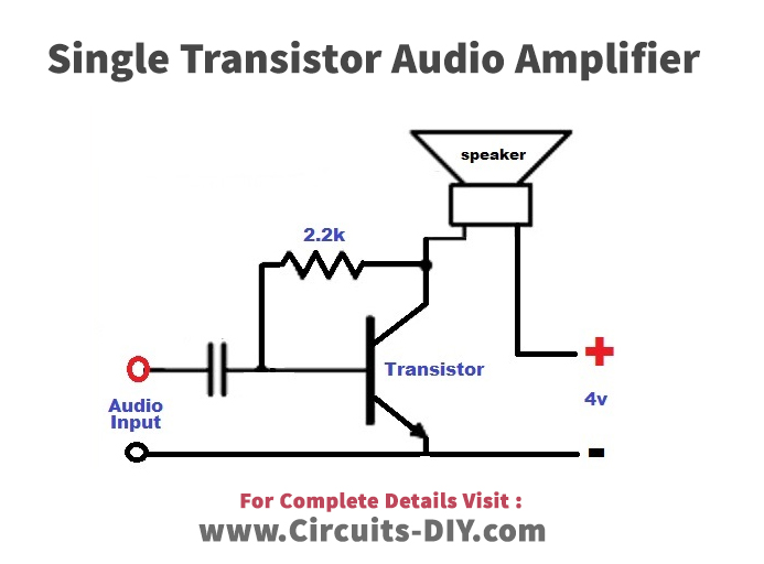
Working Explanation
This single-transistor amplifier circuit is very simple to make. It employs the Simple BC547 Transistor. 2.2K Resistor is the base resistor for this transistor., provides an audio signal at the base of the transistor which allows to flow of the current between the collector and emitter. The capacitor wired in this circuit isolates the base of the transistor from the input source. Now that the base current or the voltage cannot affect the input audio. When input audio is provided at the base of the transistor, it goes into the forward stage. During the whole audio cycle that is provided to the transistor, it generates the maximum amplitude at the output side.
10. LM386 Audio Amplifier Circuit
Circuit Diagram
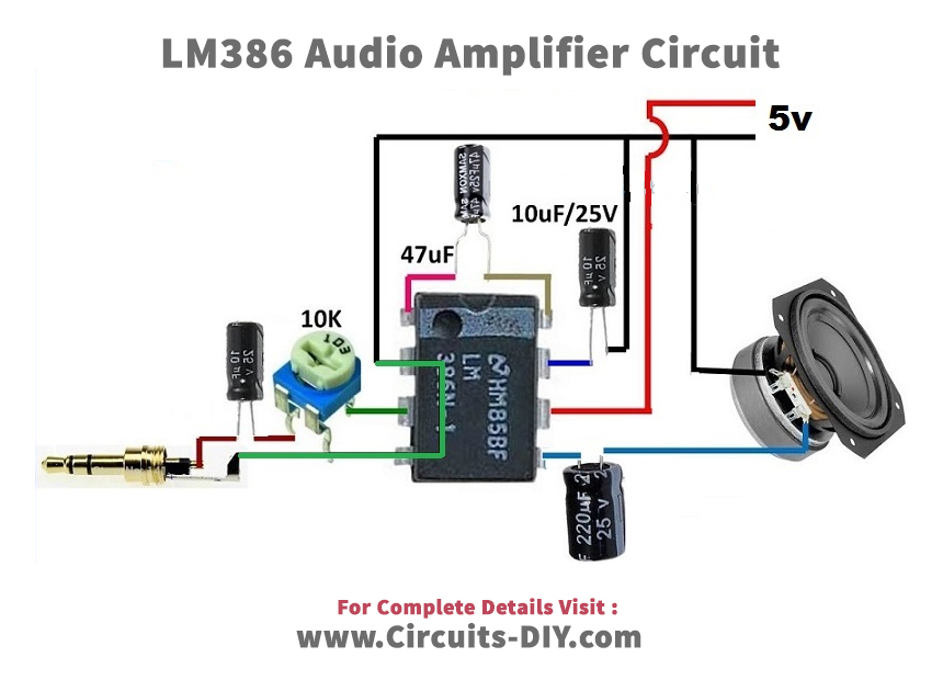
Working Explanation
In this LM386 Audio Amplifier Circuit 5V of supply is given at pin 6. Audio input is provided at the non-inverting input pin 3. A potentiometer is also wired to adjust the output audio. To set the gain of circuit 47uf the capacitor is connected between pins 1 and 8. Output is coming at pin 5 where the capacitor is wired to drive the 8 ohms, speaker.
Conclusion
In this article, we have discussed the Top 10 Simple Audio Amplifier Circuits. And, we have seen that The amplifier circuit can be built in a variety of ways using various configurations or components. Designers often employed transistors and integrated circuits to make their jobs easier and simpler. Different integrated circuits (ICs) may now be utilized to construct amplifiers.