Introduction
As technology advances rapidly, the demand for convenient and efficient electronic devices has skyrocketed. One of the essential devices in our modern lives is the cellphone, and it’s no secret that we rely on them heavily for communication, entertainment, and productivity. However, with all this usage comes the inevitable issue of battery life. Fortunately, with the development of wireless cellphone battery charger circuits, we now have a solution to keep us connected and powered up without cords and cables.
In this article, we’ll explore the inner workings of these circuits to understand how they can benefit our daily lives.
Circuit Diagram
Transmitter Circuit
Hardware Required
| S no | Components | Value | Qty |
|---|---|---|---|
| 1 | MOSFET | IRF540 | 2 |
| 2 | Resistor | R1 = 1K R2, R4 = 10K R3, R5 = 100 | 1 2 2 |
| 3 | Non Polar Capacitor | C1—C8 = 6.8nF | 2 |
| 4 | Diode | D2, D3 = 1N4148 | 2 |
| 5 | LED | Red | 1 |
| 6 | Inductor | — | 2 |
Receiver Circuit
Hardware Required
| S no | Components | Value | Qty |
|---|---|---|---|
| 1 | Voltage Regulator | 78L05 | 1 |
| 2 | Capacitor | 6.8nF, 220uF | 1, 1 |
| 3 | Resistor | 1k | 1 |
| 4 | Inductor | 1.235uH | 1 |
| 5 | Diode Bridge | D1–D4 = 1N4148 | 1 |
| 6 | LED | Red | 1 |
Working Principle
Let’s take a deep dive into constructing a wireless mobile battery charger circuit, but first, let’s understand the underlying principle that governs this circuit’s functioning. This charger circuit is primarily based on the concept of mutual inductance. According to the theory of inductive coupling, power can be transmitted wirelessly to the receiver via the electromagnetic field generated using mutual inductance. Inductance can be grouped into two categories: Mutual Inductance and Self Inductance.
In the case of mutual inductance, a conductor carrying a current is positioned strategically close to another conductor so that the magnetic flux induced by the first conductor passes on to the second conductor, resulting in voltage transfer. The magnetic flux generated is interlinked with the second conductor and acts as a medium to induce a voltage in that conductor. This phenomenon of linking conductors and inducing a voltage between them is known as inductively coupled.
How the Circuit Works
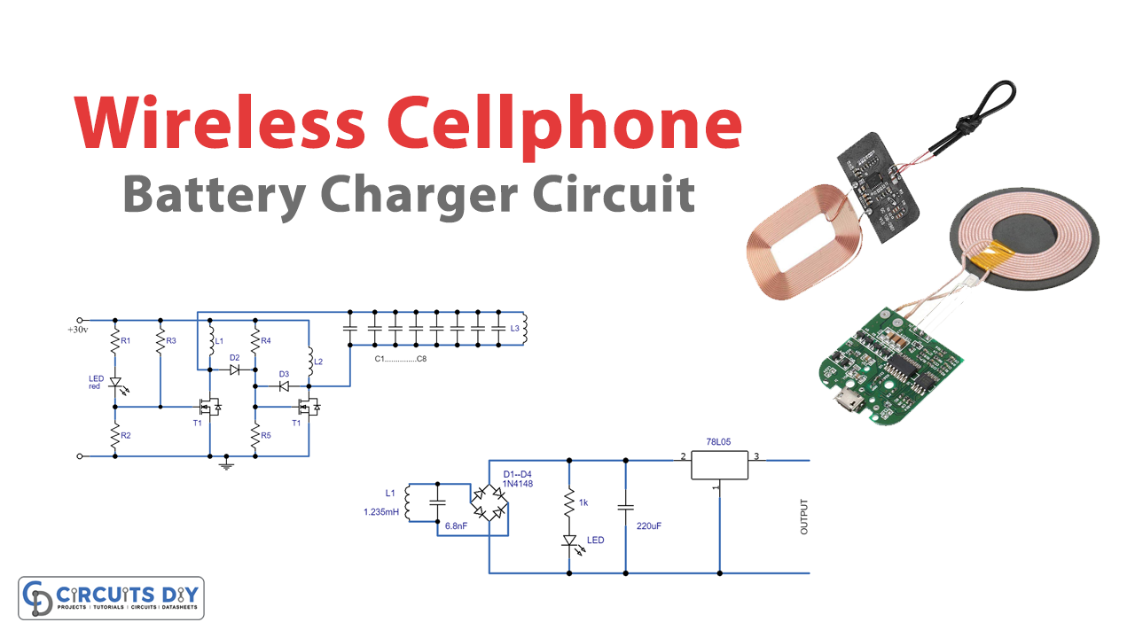
The wireless battery charger is developed using two circuits, as shown in the diagram. :
- Transmitter Circuit
- Receiver Circuit
Transmitter
The first one is the transmitter circuit that generates voltage wirelessly. It comprises an oscillator circuit, a transmitter coil, and a DC power source. The oscillator circuit includes two n-channel MOSFETs, 4148 diodes, and IRF 540. As the DC power flows to the oscillator, the coils L1 and L2 conduct the current, which drains the transistor’s terminal and simultaneously causes the voltage to appear in the transistor’s gate terminal. One of the transistors remains ON while the other stays OFF. Consequently, the voltage is boosted when released from the OFF state transistor and falls through the tank circuit, which consists of a 0.674 transmitter coil and two capacitors of 6.8nf. We can use the formula F=1/[2π√(LC)] to calculate the operating frequency.
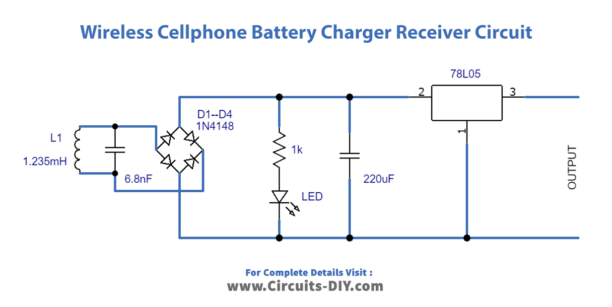
Receiver Circuit
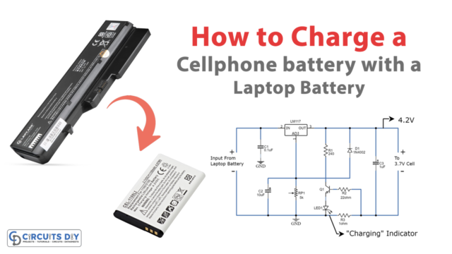
The receiving circuit is constructed using a rectifier circuit, regulator, and receiver coil. By positioning it in proximity to the inductor, the AC power is induced and then rectified by the circuit with the aid of a 6.8nf capacitor and a 1n4007 diode. The 7805 regulator then regulates the power to 5V DC, and the output is connected to the battery.
Testing
To activate the wireless cellphone charging mechanism, first, construct the circuit illustrated in the Figure (above in the circuit diagram section) and power it on. Then connect the battery charger to the circuit’s output point. Place the receiver coil near the transmitter coil to initiate battery charging.
Benefits and Uses of Wireless Cellphone Battery Charger Circuit
The wireless mobile charger is highly convenient, allowing you to charge your phone, camera batteries, and Bluetooth headset from virtually anywhere. With some modifications to the system, you can even use it to charge your car battery. However, mutual induction causes power wastage to some extent, and this design is only effective for short distances. For longer distances, you’ll need to increase the inductor.
Final Thoughts
In conclusion, wireless cellphone battery charger circuits have revolutionized how we stay connected and powered up on the go. By eliminating the need for cords and cables, these circuits have made charging our devices more convenient and hassle-free. We can only expect to see even more innovative solutions to our daily problems as technology advances. With wireless charging, we can now focus on staying connected and productive, without worrying about running out of battery life.
So let’s try this circuit and embrace the future of technology and enjoy the benefits of wireless cellphone battery charger circuits.