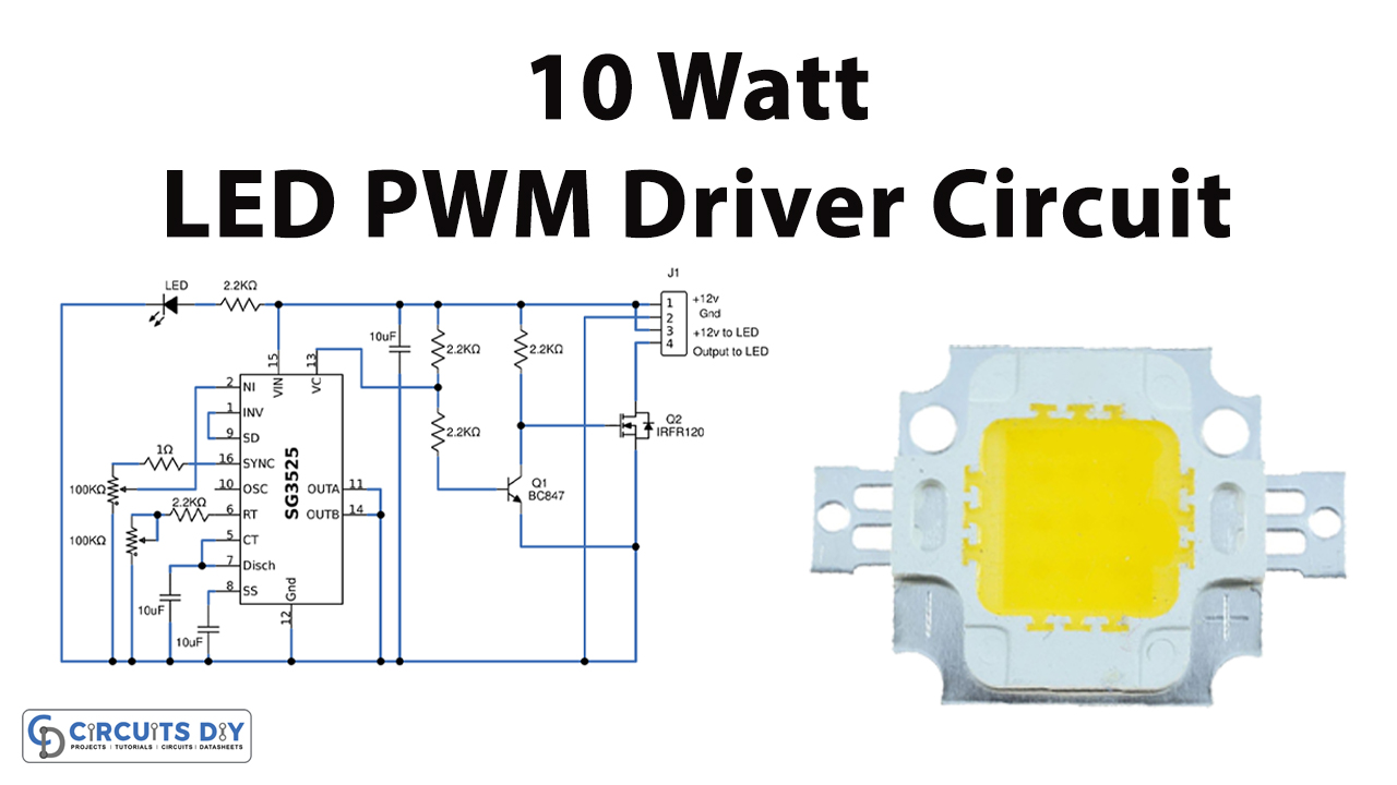
In this tutorial, we are going to make a “10W White LED PWM Driver Circuit”.
Pulse width modulation and Pulse frequency modulation are two types of techniques used in controlling integrated circuits for switch-mode power supplies. But Pulse frequency modulation technique causes some issues in switch-mode power supplies. Therefore, Pulse width modulation is a preferred technique for control circuits of switch-mode power supplies. Simple and easy 10W White LED PWM Driver Circuit designed by using IC SG3525A.
IC SG3525A is a pulse width modulator control IC that Offers improved performance and lowers external parts count when used in designing all types of switching power supplies. It offers feedback circuitry to control the output voltage by comparing the feedback signal with a reference voltage, and also has a protection circuitry that shut down the PWM signal based on the feedback current limit. It has a voltage range from 8.0V to 35V and can oscillate output frequency from 100Hz to 40KHz suitable for most LED Driver circuit designs. This IC has a latching PWM feature to prevent multiple pulses. SG3525A is used in the Dc-to-DC converter part to control the output voltage and for switching MOSFETS connected to the push-pull converter chopper.
Hardware Components
The following components are required to make LED PWM Driver Circuit
| S.no | Component | Value | Qty |
|---|---|---|---|
| 1. | IC | SG3525 | 1 |
| 2. | Resistor | 2.2KΩ, 1Ω | 5, 1 |
| 3. | Potentiometer | 100KΩ | 2 |
| 4. | Transistor | BC847, IRFR120 | 1, 1 |
| 5. | Capacitor | 10µF | 3 |
| 6. | LED | – | 1 |
| 7. | Connecting Wires | – | – |
| 8. | Power supply | 12V | 1 |
SG3525 Pinout
IRFR120 Pinout
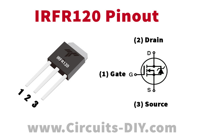
For a detailed description of pinout, dimension features, and specifications download the datasheet of IRFR120
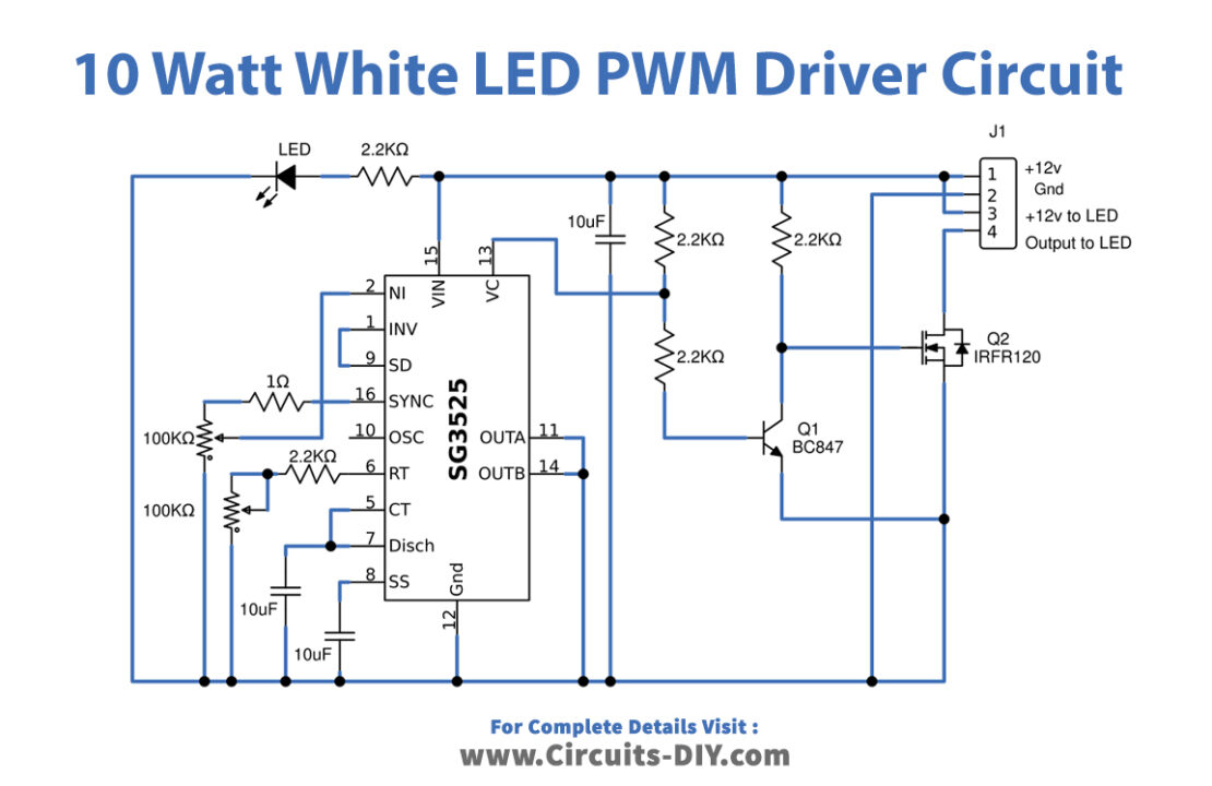
LED PWM Driver Circuit
Working Explanation
IC SG3525 is used as a 10W White LED PWM Driver. It has 16 pins; Pin 1 is an inverting pin and pin 2 is a noninverting pin. If the voltage on the inverting pin is greater than the voltage on the non-inverting pin, the duty cycle increases, and if the voltage on the non-inverting pin is greater than the inverting pin, the duty cycle decreases. So, you can use one pin for feedback through the voltage divider and one pin for the setting of a reference voltage. Pin 3 is used for the synchronization of two waves. Pin 4 is the output of an oscillator. Pin 5, 6, and 7 are used to set the frequency of PWM. Here oscillator frequency range is decided by adjusting the value of oscillator timing Resistor RT, Oscillator timing Capacitor CT and discharge resistor. Pin 8 SS is used for soft starting for enabling output after some time.
Greater the value of capacitance connected to pin 8, the greater the soft-start time. Pin 9 is a compensation pin used with feedback to avoid rapid fluctuations in output voltage with the change in load or input voltage. Pin 10 is a shutdown pin. If shutdown pin = 0 it will work and if shutdown pin = 1 means connected with 5 volts it will remain in shutting down mode.
Pins 11 and 14 are output pins. These pins provide input to MOSFETs. Pin 13 and 15 are power pins. Vc should be between 5-35 volt and Vin should be between 8-35 volt. Pin 16 is a reference pin and it is used to set reference voltage through pin 1 or 2. It can also be used to give 5 volts to shut down the pin in case you want to shut down SG3525A through a push button. In this LED driver circuit one 10 watts white LED is connected at +12V to the LED pin and output to the LED cathode. MOSFET IRFR120 acts as a switching device and drives the LED according to the output from the VC pin through the Q1 transistor. In this circuit, by varying the value of RV1 and RV2 we can adjust the dimming and brightness level of the 10W LED.
Applications
It is used for brightness control in smart lighting systems by controlling voltage to LED drivers connected with LED bulbs.
Can be used for speed control of motors by varying voltage supply.