Introduction
We know that A device that can measure light intensity is a light detector circuit. But do you know that LED can be used as a light detector? This tutorial will “Use LED as a Light detector circuit.”When LEDs detect light, they generate a voltage that matches the typical voltage drop. Only the super-bright ones can produce a higher output because their crystal is more effective at converting light into electricity, even though the current they create is relatively minor.
The circuit produces an output signal that displays the measured light’s intensity. Interestingly, it’s a simple project that is suitable for beginners.
Hardware Required
| S.no | Component | Value | Qty |
|---|---|---|---|
| 1. | IC | TL071 | 1 |
| 2. | NPN Transistor | BC337 | 1 |
| 3. | NPN Transistor | BC547 | 1 |
| 4. | Indicator LED | – | 1 |
| 5. | LED as a Light Sensor | – | 1 |
| 6. | Potentiometer | 10K | 1 |
| 7. | Resistor | 330Ω, 1KΩ, 3.3KΩ, 470KΩ, 10MΩ | 1, 2, 1, 1, 1 |
| 8. | Battery | 9V | 1 |
| 9. | 2-Pin Connector | – | 1 |
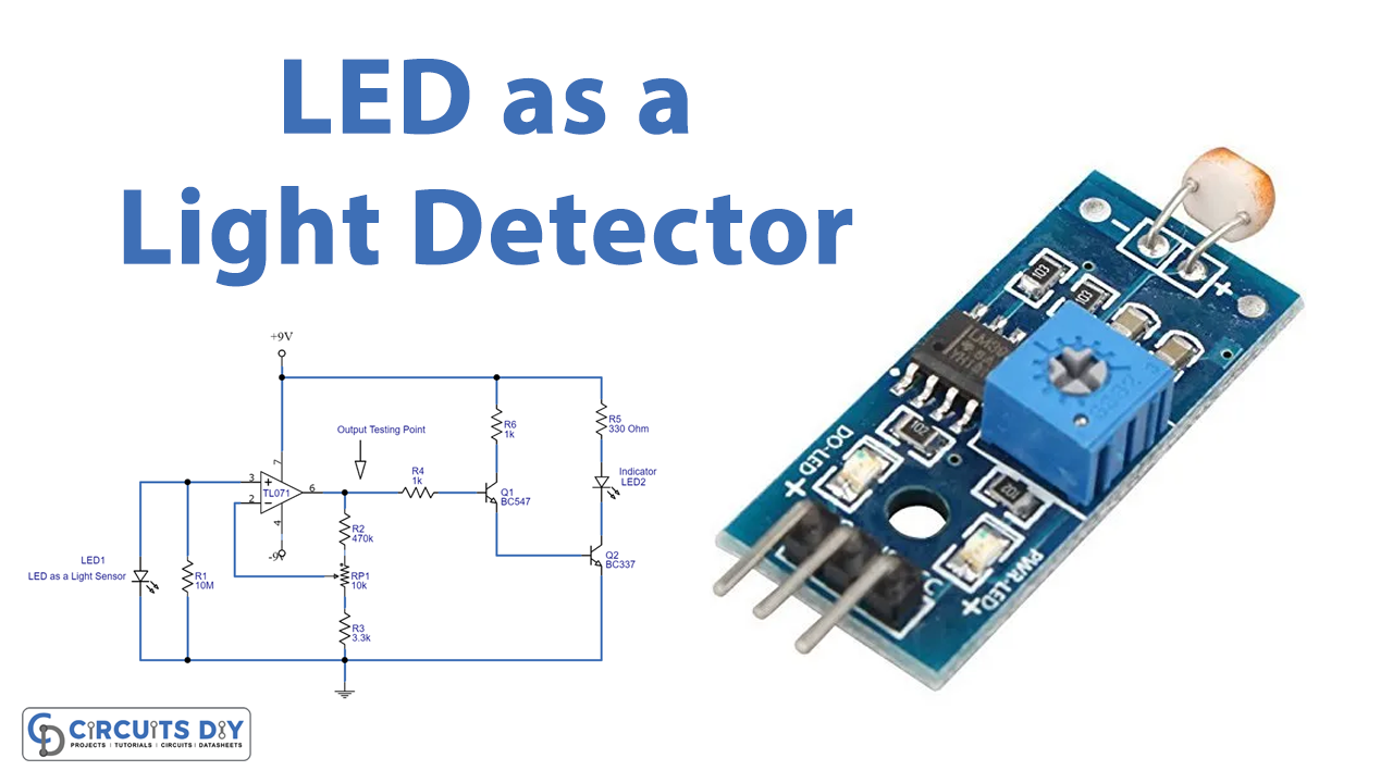
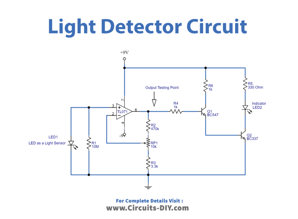
Circuit Diagram
Working Explanation
The circuit employs a 5mm clear RED LED1 and a 5mm white LED2 as a light sensor and an indicator, respectively. Here, the detected signal is amplified using a JFET input operational amplifier (TL071) powered by a dual power source (+9V to -9V). BC547 and BC337 NPN transistors drive the indicator LED, and when the sensor LED is dark, the output of TL071 changes to a high state, turning on Q1 and Q2, which then turns on the indicator. When the light strikes LED1, the output state of TL071 changes to low, and the transistors Q1 and Q2 turn off, removing the bias from the indicator and turning LED2 off. At the output testing point in the circuit schematic, we can obtain variable output voltage based on the intensity of the light signal.
Application and Uses
- Security alarm systems
- High-sensitive power savers for streetlights
- Home lighting
- Automatic switching for appliances