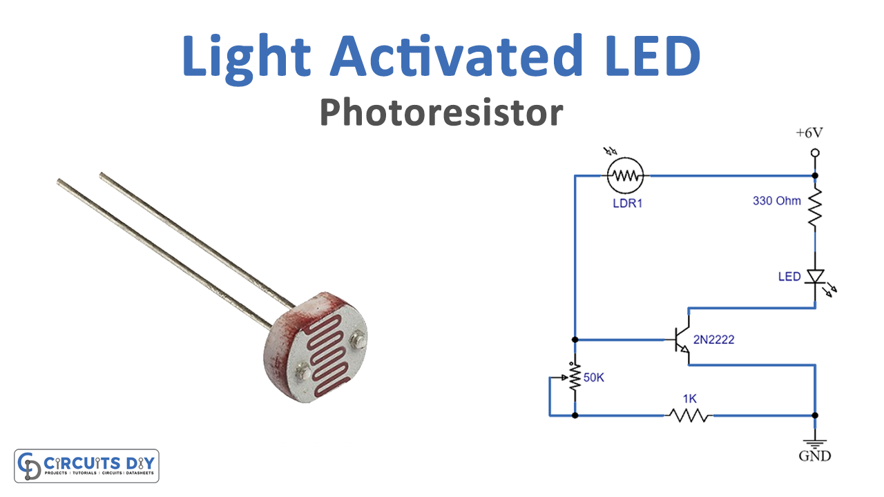
In this article we are going to demonstrate a simple and interesting project of a light-activated LED circuit, using an LDR and photoresistor. This circuit is very easy to build and beginner-friendly we are using only six components. The photoresistor is used for the purpose of sensing light. When the light falling on the photoresistor has the maximum intensity the resistance will be minimum and it will let the current pass through the circuit and in dark the resistance will be maximized therefore LED will be OFF.
The purpose of the transistor is to provide switching. It conducts the current across the collector-emitter path when voltage is applied at the base. If there is no voltage the transistor will switch to the OFF state and turns ON when voltage is applied.
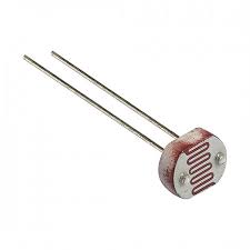
Hardware Components
The following components are required to make Light Activated LED Circuit
| S.no | Components | Value | Qty |
|---|---|---|---|
| 1. | Transistor | 2N2222 | 1 |
| 2. | Photoresistor (LDR) | – | 1 |
| 3. | Variable Resistor | 50K | 1 |
| 4. | Resistor | 330Ω, 1KΩ | 1, 1 |
| 5. | Power Supply | 6V | 1 |
| 6. | LDR | – | 1 |
2N2222 Pinout
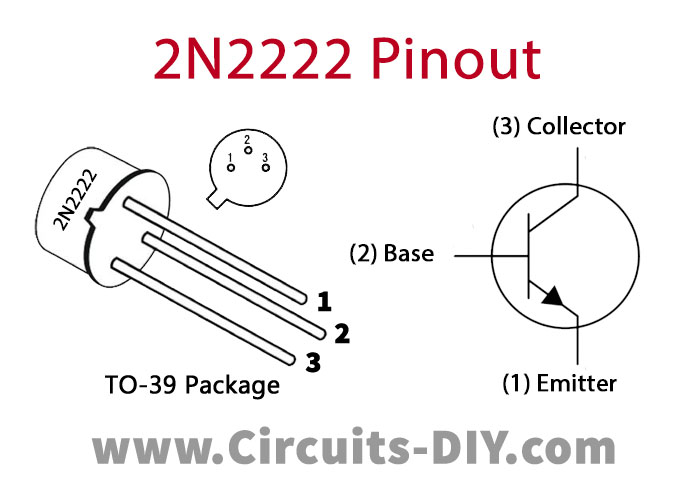
For a detailed description of pinout, dimension features, and specifications download the datasheet of 2N2222
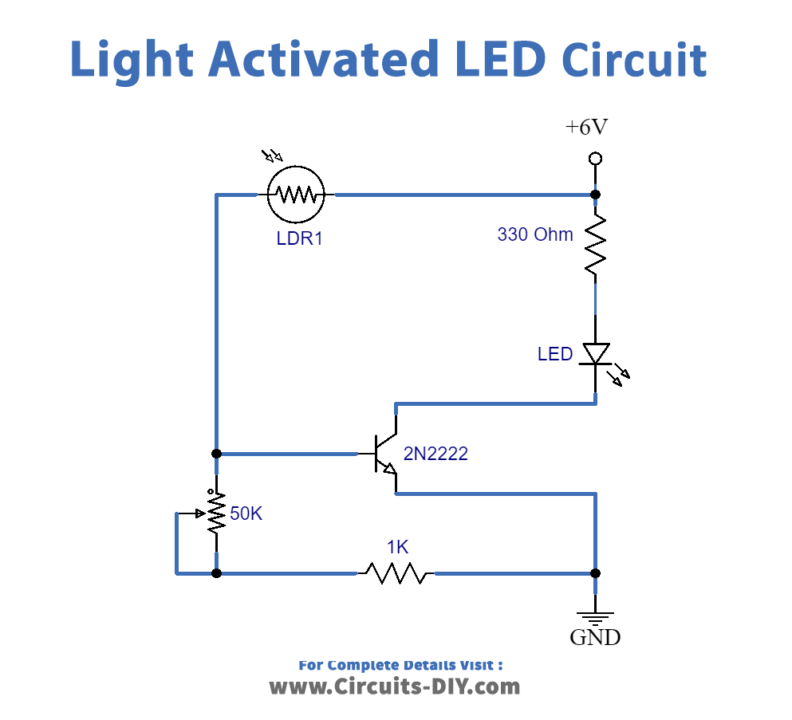
Light Activated LED Circuit
Working Explanation
The operating voltage of this circuit is 6 volts, you can use four 1.5 volts batteries of any size to make this circuit work. When any type of light such as a bulb, lamp, or sunlight falls on the photoresistor its resistance will be minimized and it will let the current pass through it and feed into the base of the transistor 2N2222. The transistor will be switched ON and the LED will light up.
The variable resistor of 50K is used to adjust the amount of light of LED according to you. The 1K resistor is used to protect the photoresistor from connecting directly to the supply when resistance is minimized. Another resistor of 330 ohms is used as a current limiter for the LED.
Applications and Uses
- Security Purposes
- Toys
- Electronic Projects
- Lamps

