Overview
Many people overlook the fact that several voltage regulator ICs come with an upper limit, typically around 35 V, for the input voltage they can manage. This restriction primarily applies to fixed-output voltage types. Even adjustable voltage regulators come with a maximum voltage specification, often around 40 V, concerning the input and output. Consequently, in a fault scenario where the output experiences a short circuit, the input voltage must be restricted to this level.
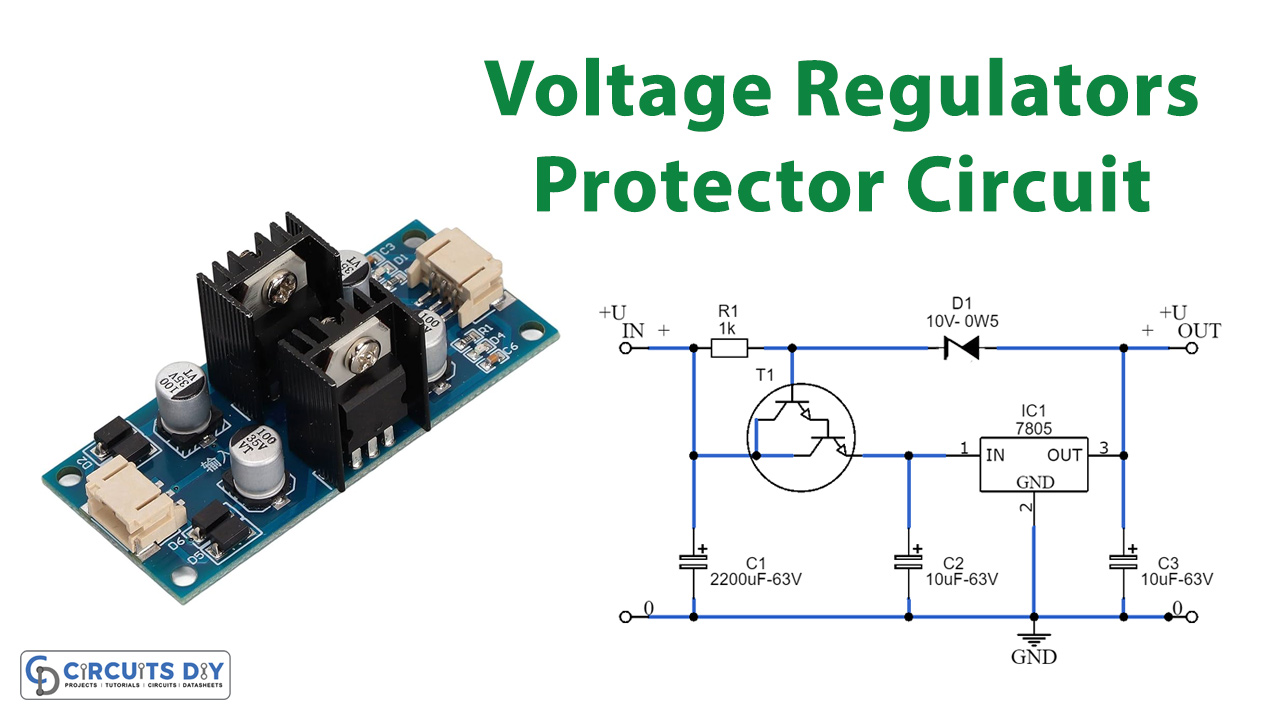
The following schematic demonstrates a method to utilize such regulators in scenarios involving higher input voltages. Although this solution necessitates an additional three components, it remains straightforward and can be assembled using readily available parts. The voltage across the regulator gets capped by the T1 and zener diode D1 combination, ensuring it functions correctly with loads up to its maximum rated capacity. R1 facilitates the necessary operating current for D1 and biases T1 appropriately.
Opting for a Darlington type for T1 is advisable to maintain a reasonably high value for R1. With a 60 V input voltage, the current passing through D1 is a mere 10 mA. We conducted tests to assess the circuit’s behavior under no-load conditions. Surprisingly, even with a 60 V input, the nominal output voltage of 5.02 V only rose to 5.10 V. In our trials, we employed a BDV65B for T1 along with a 4.7 kΩ value for R1.
To ensure true short-circuit protection at a 60 V input voltage, it’s crucial to select a transistor that remains within its safe operating range under the maximum input voltage and the regulator’s short-circuit current, which can exceed 2 A. Both the BDV65B and TIP142 fail to meet this criterion. The BDV65B’s maximum voltage is 40 V, and for the TIP142, it’s 50 V. If the transistor experiences breakdown, it will lead to the regulator’s failure as well. We confirmed this through experimental validation.
Hardware Components
You’ll need the following hardware components to get started:
| S.no | Components | Value | Qty |
|---|---|---|---|
| 1 | Integrated Circuit IC | IC1=7805 | 1 |
| 2 | Darlington Transistor | T1 = BDV65B | 1 |
| 3 | Non-Polar Capacitors | C1=220uF-63v C2,C3=10uF-63v | 1 2 |
| 4 | Diode | 0.5w | 1 |
| 5 | Resistor | R1= 4.7 k | 1 |
Schematic

Adding SOA protection for T1 is one approach, though it essentially means safeguarding the safeguard. Another avenue involves loosening the requirements. To achieve this, R1 needs to supply ample current to ensure T1 receives sufficient current during a short circuit, keeping the voltage across T1 lower. However, this adjustment doesn’t have a significant practical impact and also raises the minimum load. Furthermore, adequate cooling for both T1 and IC1 is imperative based on the load requirements.
The ripple suppression effect of the protection circuit is minimal since T1 already stabilizes the input well. However, it’s crucial to consider that the current passing through D1 also flows through the output. Additionally, the presence of C2 needs consideration. In scenarios where an adjustable voltage regulator like the LM317 is employed, and the output voltage exceeds 40 V, C2 may momentarily push the voltage above 40 V during a short circuit, potentially damaging the IC. In such instances, alternative solutions or different types of voltage regulators may be necessary.