Introduction
Pulse sensors are used in several projects for athletes, gaming, home appliances, and mobile phone developers where there is a need for reading heart rate data. In this tutorial, I’ll focus on one of the low-power plug-and-play pulse sensors for Arduino.
What is a Pulse Sensor?
A pulse sensor is a device used to detect a change in the volume of a blood vessel that occurs when the heart pumps blood. This volume change is called a pulse wave and is the basis of determining heart rate.
PCBWay commits to meeting the needs of its customers from different industries in terms of quality, delivery, cost-effectiveness, and any other demanding requests. As one of the most experienced PCB manufacturers in China. They pride themselves to be your best business partners as well as good friends in every aspect of your PCB needs.
Hardware Components
You will require the following hardware for the Heart Rate Monitor.
| S.no | Component | Value | Qty |
|---|---|---|---|
| 1. | Arduino UNO | – | 1 |
| 2. | USB Cable Type A to B | – | 1 |
| 3. | DC Power for Arduino | – | 1 |
| 4. | Pulse Sensor | – | 1 |
| 5. | Jumper Wires | – | 1 |
Pulse Sensor Overview
The Pulse Sensor Amped is a plug-and-play heart-rate sensor for Arduino. It can be used by students, artists, athletes, makers, and game & mobile developers who want to easily incorporate live heart-rate data into their projects.It essentially combines a simple optical heart rate sensor with amplification and noise cancellation circuitry making it fast and easy to get reliable pulse readings. Also, it sips power with just 4mA current draw at 5V so it’s great for mobile applications.
Pulse Sensor Pinout
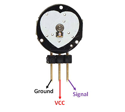
Pulse Sensor with Arduino
I’ll now show you a simple practical application of this sensor where you can display the pulse waveform and the corresponding heart rate in beats per minute (BMP) reading on an SSD1306 OLED.
Before proceeding you should know how to use the SSD1306 OLED with Arduino and in case you need assistance on this issue you can visit my other tutorial where I have written in-depth about the SSD1306 OLED and its use with Arduino:
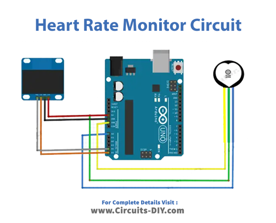
The setup is as shown in the schematic below. The SSD1306 OLED uses I2C communication and therefore we simply connect the SDA and SCL to A4 and A5 for Arduino UNO
Schematic
Make connections according to the circuit diagram given below.
Wiring / Connections
| Arduino | Pulse Sensor | OLED |
|---|---|---|
| 5V | VCC | VCC |
| GND | GND | GND |
| A0 | SIG | |
| A4 | SCL | |
| A5 | SDA |
Installing Arduino IDE
First, you need to install Arduino IDE Software from its official website Arduino. Here is a simple step-by-step guide on “How to install Arduino IDE“.
Installing Libraries
Before you start uploading a code, download and unzip the following libraries at /Progam Files(x86)/Arduino/Libraries (default), in order to use the sensor with the Arduino board. Here is a simple step-by-step guide on “How to Add Libraries in Arduino IDE“.
Code
Now copy the following code and upload it to Arduino IDE Software.
#include <Adafruit_SSD1306.h>

#define OLED_Address 0x3C
Adafruit_SSD1306 oled(128, 64);

int x=0;
int lastx=0;
int lasty=0;
int LastTime=0;
int ThisTime;
bool BPMTiming=false;
bool BeatComplete=false;
int BPM=0;
#define UpperThreshold 518
#define LowerThreshold 509

void setup() {
  oled.begin(SSD1306_SWITCHCAPVCC, OLED_Address);
  oled.clearDisplay();
  oled.setTextSize(2);
}


void loop()
{
  if(x>127)
  {
    oled.clearDisplay();
    x=0;
    lastx=x;
  }

  ThisTime=millis();
  int value=analogRead(0);
  oled.setTextColor(WHITE);
  int y=60-(value/16);
  oled.writeLine(lastx,lasty,x,y,WHITE);
  lasty=y;
  lastx=x;
  // calc bpm

  if(value>UpperThreshold)
  {
    if(BeatComplete)
    {
      BPM=ThisTime-LastTime;
      BPM=int(60/(float(BPM)/1000));
      BPMTiming=false;
      BeatComplete=false;
      tone(8,1000,250);
    }
    if(BPMTiming==false)
    {
      LastTime=millis();
      BPMTiming=true;
    }
  }
  if((value<LowerThreshold)&(BPMTiming))
    BeatComplete=true;

    // display bpm
  oled.writeFillRect(0,50,128,16,BLACK);
  oled.setCursor(0,50);
  oled.print(BPM);
  oled.print(" BPM");
  oled.display();
  x++;
}
Applications
- Athletes
- Gaming
- Home appliances
- Mobile phone developers etc
Conclusion.
We hope you have found this Heart Rate Monitor Circuit very useful. If you feel any difficulty in making it feel free to ask anything in the comment section.
Related posts:
 LED Chaser Circuit using Transistors - Electronics Projects
 How To Make A Smart Door Lock Using An IR LED Pair & Servo Motor
 Subwoofer Audio Amplifier Using TDA2003 IC
 LED Chaser Circuit Using CD4017 Decade Counter IC
 How To Make An RFID Card Reader Without Using An Arduino
 Heartbeat Sensor Circuit Using LM358 - Electronics Projects