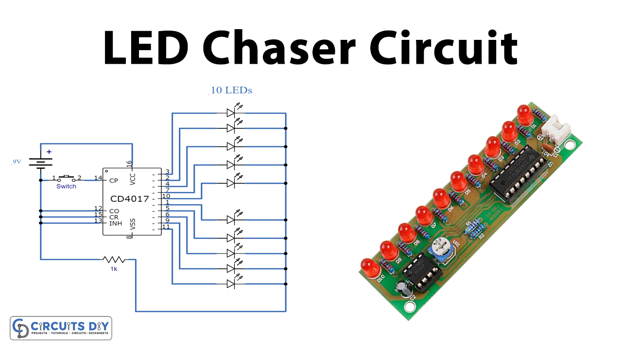
An LED chaser circuit (ring counter) is a repeating sequencer usually made by combining a clock with a counter. The clock can be any of several types including discrete components such as an astable multivibrator, inverter, logic gate, a pushbutton, or a dedicated timer IC such as a NE555. The counter can be any of several types including 4-bit, 8-bit, decade, or shift registers, depending on the number of outputs and other features. In this project, we are going to build a simple LED chaser circuit using a CD4017 Decade counter IC.
CD4017 IC is a 16-pin CMOS decade counter/Divider with 10 outputs. It is also known as the ‘Johnson 10 stage decade counter’. It has 10 decoded outputs that give output signals one by one in sequence when a clock signal from the clock input is given.
Hardware Components
The following components are required to make LED Chaser Circuit
| S.no | Component | Value | Qty |
|---|---|---|---|
| 1. | Decade Counter IC | CD4017 | 1 |
| 2. | Resistor | 1k | 1 |
| 3. | Push Button | – | 1 |
| 4. | LED | 5mm | 10 |
| 5. | Battery | 9v | 1 |
| 6. | Connecting Wires | – | 1 |
| 7. | Breadboard | – | 1 |
CD4017 Pinout
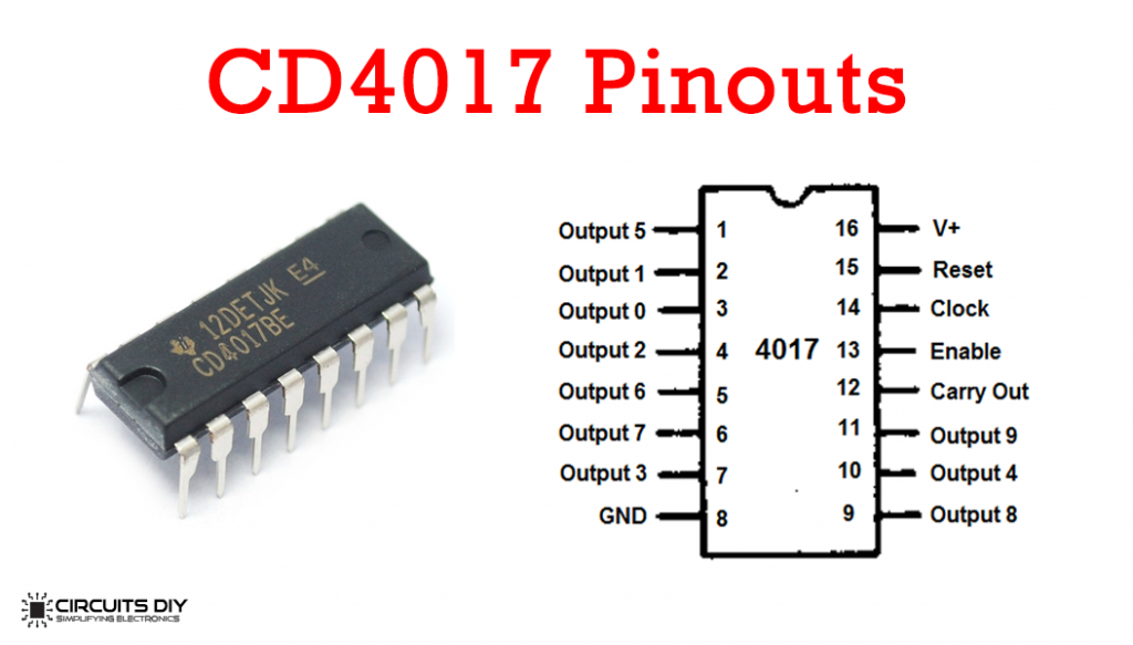
For a detailed description of pinout, dimension features, and specifications download the datasheet of CD4017
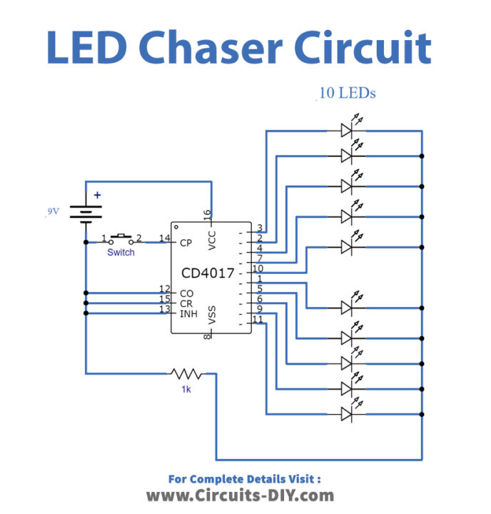
LED Chaser Circuit
Working Explanation
A pushbutton is connected to the clock input of the CD4017 decade counter IC. CD4017 has 10 output pins and each pin is connected to an LED. By default, the first output pin is on or high and the rest are off.
Each time the clock input pin of 4017 IC detects a rise in voltage (from low to high), it turns off the current output and turns on the next sequential output. This swapping of outputs which looks like the LEDs are chasing each other, continues until the last LED and then the output resets back to the first LED.
Applications
- Widely used in places such as advertising displays and in running-light ‘rope’ displays in small discos, etc.