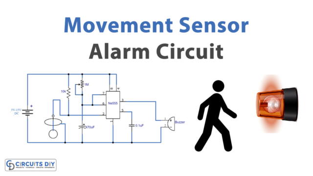
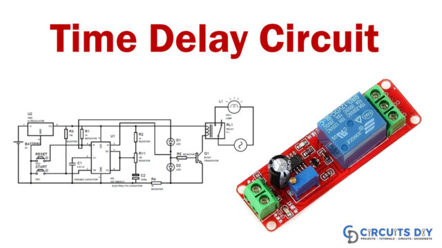
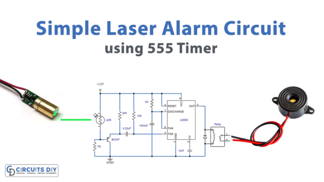
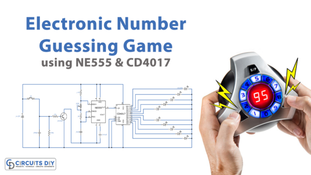
Police lights are flashing lights that are used by police cars, ambulances, fire trucks, and military vehicles for emergency purposes. In this tutorial, we will learn how to make a police light circuit by using a 555 Timer and a decade counter IC CD4017. This circuit simulates the police car lights by alternately flashing red and blue color LEDs.

Hardware Components
The following components are required to make Police Light Circuit
| S. NO | Component | Value | Qty |
|---|---|---|---|
| 1. | IC | CD4017 | 1 |
| 2. | IC | NE555 Timer | 1 |
| 3. | NPN Transistor | 2N2222 | 2 |
| 4. | Capacitor | 10uF | 1 |
| 5. | Resistor | 220, 10k, 1k | 7, 1, 1 |
| 6. | Battery | 6v | 1 |
| 7. | Breadboard | 1 | |
| 8. | Connecting Wires | 1 | |
| 9. | LED | 5mm | 4 |
555 IC Pinout

For a detailed description of pinout, dimension features, and specifications download the datasheet of 555 Timer
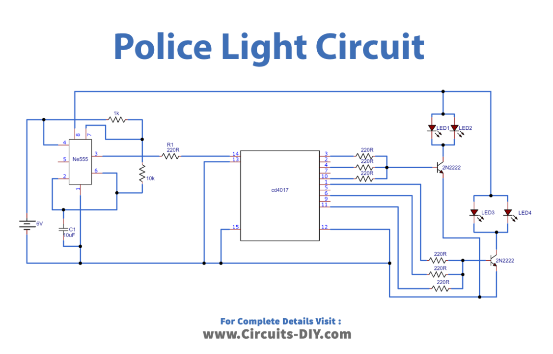
Police Light Circuit
Connection
- Connect Pin 8 of IC (555 Timer) to VCC.
- Connect Pin 4 of the IC (555 Timer) to GND.
- Use a jumper wire to connect Pin 6 and Pin 2 of IC (555 Timer).
- Use a jumper wire to connect Pin 4 and Pin 8 of IC (555 Timer).
- Connect the 10K Resistor between Pin 6 and Pin 7 of IC (555 Timer).
- Connect the 10uF Capacitor between Pin 1 and Pin 2 of IC (555 Timer).
- Connect the 1K Resistor between Pin 7 and Pin 8 of IC (555 Timer).
- Connect Pin 8 of IC (CD4017) to GND
- Connect Pin 16 of IC (CD4017) to VCC
- Connect 220 Ω Resistor between Pin 3 of 555 Timer and Pin 14 of CD4017
- Connect Pin 13 and Pin 15 of IC (CD4017) to GND
- Connect the Anode terminal of all LEDs to VCC
- Connect the Emitter of both Transistors to GND
- Connect the Collector of each Transistor to the Cathode terminal of each LED
- Connect three 220 Ω Resistors from Pin 3,4,10 of IC (CD4017) to the Base of one Transistor
- Connect the other three 220 Ω Resistors from Pin 1,6,11 of IC (CD4017) to the Base of the Second Transistor
Working Explanation
In this circuit, 555 Timer runs in Astable mode. It generates constant output in the form of square waves via pin 3. The width of the pulse can be varied by changing the value of the resistors (1K &10K) and the capacitor (10uF). The 4th Pin of the 555 timers is connected to VCC to avoid sudden resets.
The CD 4017 Decade counter counts the number of incoming pulses from the 555 timers. A high pulse received on the reset pin clears the count to zero. The output of CD4017 is connected to the base of the transistor, which amplifies the current and then sends it to the LEDs. 220 Ω Resistors are connected to the LEDs in order to protect them from high voltage.
Application
- This circuit can be used by police cars, ambulances, and military vehicles for emergency purposes
- We can use it as an LED flasher circuit by doing some modifications