Here, in this DIY, we are making a “Simple Time Delay Circuit Using 555 Timer IC.” This circuit comprises 2 switches one for starting the delay time and the other for reset. It additionally has a potentiometer to modify the time delay, where you can expand or diminish the time delay by simply pivoting the potentiometer.
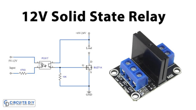
Here we have utilized a 9 V battery and 5V discretionary Relay for changing the AC load. A 5 V voltage controller is utilized for giving a 5 V power source to the circuit.
Hardware Component
The following components are required to make Time Delay Circuit
| S. no | Component | Value | Qty |
|---|---|---|---|
| 1 | Resistor | 1KὨ, 10KὨ, 1000K Var | 1, 1, 1 |
| 2 | IC | 555 timer | 1 |
| 3 | LED | 2 | |
| 4 | Capacitor | 0.01uF, 200uF | 1, 1 |
| 5 | Push Button | – | 2 |
| 6 | Breadboard | – | 1 |
NE555 IC Pinout

For a detailed description of pinout, dimension features, and specifications download the datasheet of 555 Timer
Time Delay Circuit
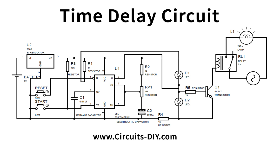
Circuit Operation
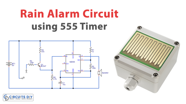
As we clarified over, the time delay for the semi-stable state is relying on the value of the Timing capacitor and resistor. As you change the estimation, the time delay for the semi-stable state will likewise be changed. Here the Blue LED sparkles in a semi-stable state for a specific time, and Red LED shines in a stable state. So here we have supplanted this timing Resistor with the Variable Resistor, so we can alter the time delay just by pivoting the handle of the potentiometer on the board itself. Here we have additionally associated a Relay for triggering the AC apparatus after a time delay.
At the point when you press the Start button, the timer starts, and the Blue LED turns on, and after the specific time, the 555 clock goes into a stable state, where the Red LED turns ON, and the blue LED turns off. You can increment and lessen the time delay by utilizing the potentiometer
Applications and Uses
This simple time delay circuit is used to control the events which are based on time.