Commonly, the anti-agents we have employed at our homes and offices as a Mosquito repellent like mats, coils, sprays, and creams are often harmful. For example, mosquito repellent creams and oils can cause unfavorable effects on the skin like hypersensitive responses. Likewise, coils, sprays, and mats can create poisonous exhaust when heated and cause breathing difficulty. In this regard, and electronic mosquito repellent is fascinating and safe for human health.
In retail markets, electronic mosquito repellent is easily accessible. However, the price range might affect your budget. Therefore, these mosquito repellers’ DIY project is pretty simple. We can assemble a primary mosquito repellent circuit at home effectively by utilizing the 555 timer IC and not many other ordinarily accessible parts.
Here in this article, I have planned to show you how to make a primary mosquito repellent circuit, delivering a sound of around 40 kHz.

Hardware Components
The following components are required to make Electronic Mosquito Repellent Circuit
| S.no | Component | Value | Qty |
|---|---|---|---|
| 1. | Connecting wires | – | – |
| 2. | Breadboard | – | 1 |
| 3. | Battery | 9 V | 1 |
| 4. | Capacitor | 0.01 µF | 1 |
| 5. | Resistor | 1K, 1.3K, 10K Var | 1, 1, 1 |
| 6. | Buzzer | – | 1 |
| 7. | IC | NE555 Timer | 1 |
NE555 IC Pinout

For a detailed description of pinout, dimension features, and specifications download the datasheet of 555 Timer
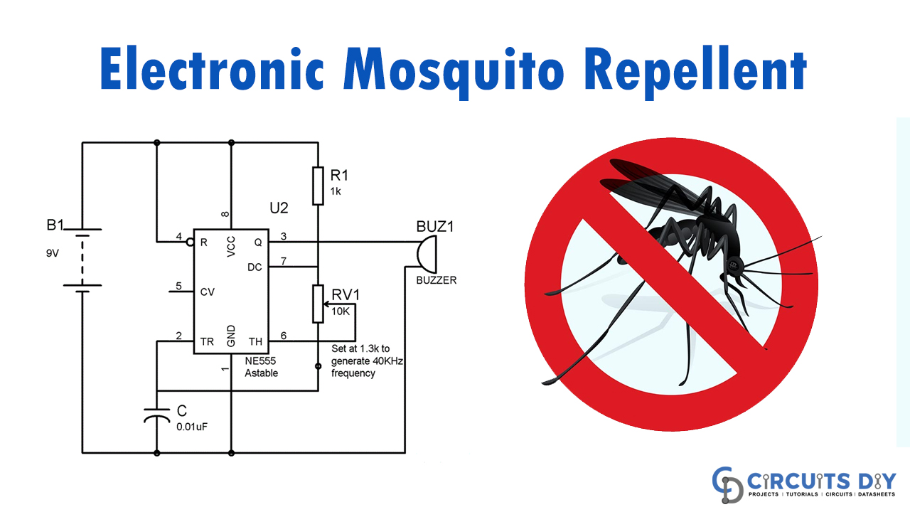
Electronic Mosquito Repellent Circuit
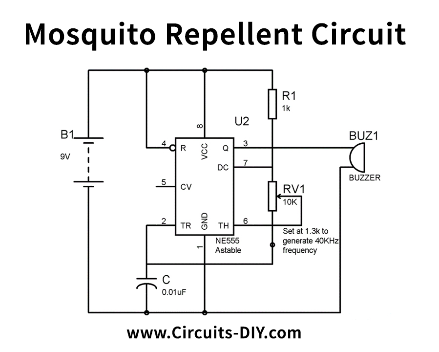
Circuit Operation
As appeared in the above circuit schematic, we have employed a 555 timer IC in Astable mode to deliver a 40 kHz frequency sound. We have likewise associated a Buzzer at the yield (PIN 3) of the 555 timer IC with the goal that a sound of the wanted frequency can be created. However, we should note here that we need a HIGH-frequency Piezo signal because the piezo sensor needs a high-frequency pitch to detect the object. Likewise, note that we probably won’t have the option to hear the sound created by the circuit for what it’s worth past our perceptible range.
We can figure the estimation of resistors and capacitors to deliver wavering of 40KHz frequency by given formulae:
F = 1.44/((R1+R2*2)*C)
For our calculations, we have utilized;
R1= 1K
R2(RV1) = 1.3 K (variable resistor of 10k, set at 1.3K with the assistance of multimeter)
C = 0.01uF
So now
F = 1.44/{(1 + 2*1.3)*1000} * 0.01uF
F = 1.44 * 100000/3.6 = 40000 = 40KHz
We can expand the estimation of resistor R1 or R2 to diminish the frequency.
Applications and Uses
- To repel mosquitos