Overview
There are numerous circuits available for low-voltage regulators. However, when it comes to higher voltages, like those needed for valve circuits, things change. That’s why we opted to create this straightforward regulator capable of handling these voltages. This circuit pairs well with the quad power supply for the hybrid amp, which you can find in another section of this publication.
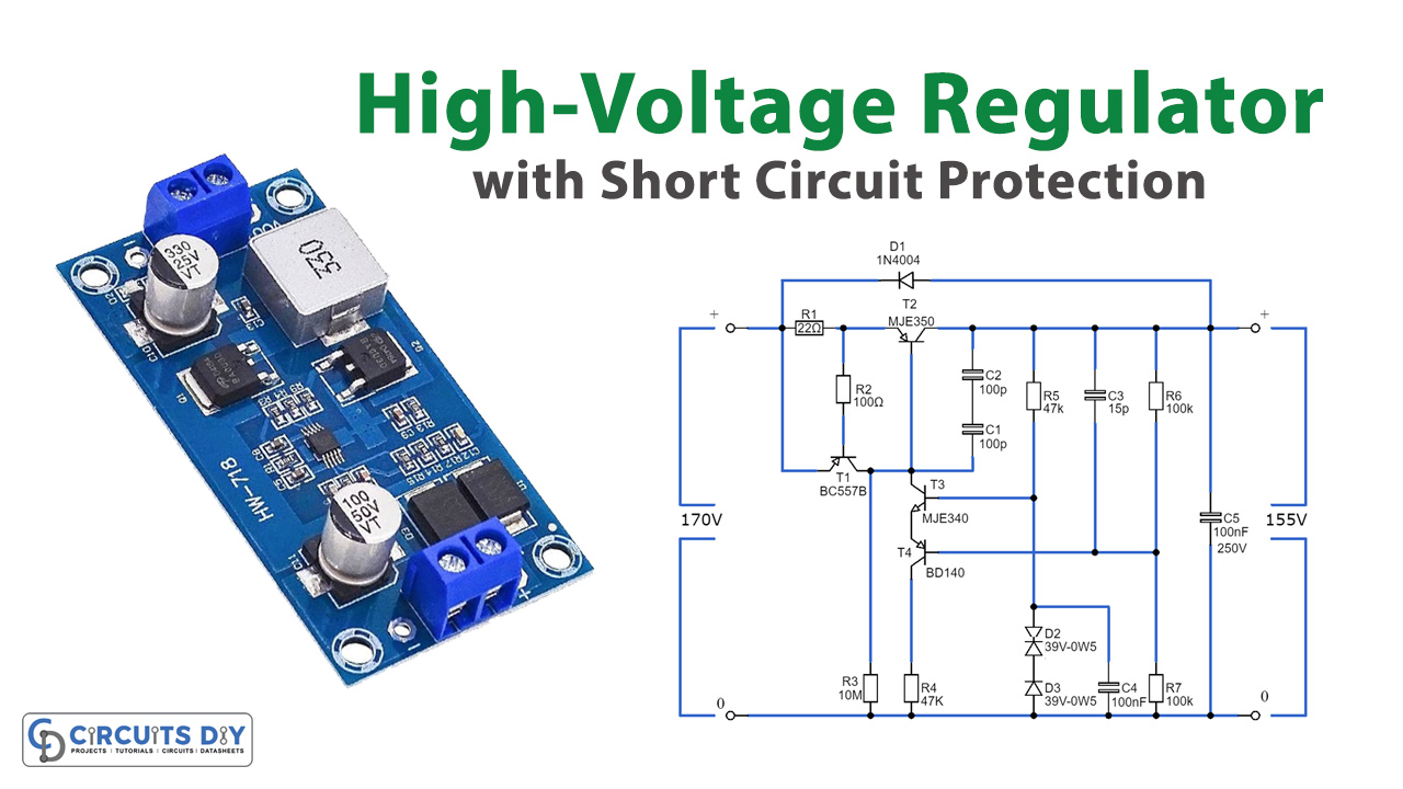
The regulator itself comprises just three transistors, with an additional fourth for current limiting. It operates as a positive series regulator, utilizing a PNP transistor (T2) to minimize voltage drop. Its functioning is quite simple: when the output voltage decreases, T4 pulls T3’s emitter down, making T2 work harder and raising the output voltage. R4 manages the base current of T2, while C1 and C2 enhance circuit stability.
These capacitors are in series to prevent excessive voltage across each during startup or short circuits. For C1-C3, ensure a minimum rating of 100 V. D1 safeguards T2 against negative voltages that might occur during short circuits or when large capacitors are connected.
For the reference voltage, we use two series-connected zener diodes rated at 39 V each, totaling 78 V at T3’s base. Because R6 equals R7, the output voltage doubles to around 155 V. T4 acts as a buffer for the potential divider R6/R7, allowing higher resistor values without affecting the voltage due to T2’s base current. This circuit lacks temperature compensation but suffices for its intended use.
Hardware Components
You’ll need the following hardware components to get started:
| S.no | Components | Value | Qty |
|---|---|---|---|
| 1 | Transistors | T1 = BC557B T2 = MJE350 T3 = MJE340 T4 = BD140 | 1 1 1 1 |
| 2 | Diodes | D1 = 1N4004 D2 ,D3 = 39V0W5 | 1 2 |
| 3 | Non-Polar Capacitors | C1 ,C2 = 100p C3 = 15p C4 = 100n C5 = 100n 250v | 1 1 1 1 |
| 4 | Resistors | R1 = 22Ω R2 = 100Ω R3 = 10m R4 ,R5 = 47k R6 ,R7 = 100k | 1 1 1 2 2 |
Schematic