In this tutorial, we are going to make a “PIR Motion Detector Circuit”.
We need security everywhere to protect property or confidential information from others. A motion detector is an electronic device that utilizes a sensor to detect nearby motion, which is a sensor sensing a human motion and then transmitting the signal. An active motion detector contains an optical, microwave, or acoustic sensor, as well as a transmitter. However, a passive one contains only a sensor and only senses a signature from the moving object via emission or reflection. As we are going to make a motion detector alarm circuit by using a PIR sensor. Passive Infrared Sensor (PIR) is a very useful module, used to build many kinds of Security Alarm Systems and Motion Detectors. It is called passive because it receives infrared, not emits. PIR sensors are sensitive to a person’s skin temperature through emitted black-body radiation at mid-infrared wavelengths, in contrast to background objects at room temperature. Here we design this circuit with PIR, relay, and other few available components, when the PIR sensor detects a person moving it will trigger the relay and makes the electric bulb glow.
Hardware Required
| S.no | Component | Value | Qty |
|---|---|---|---|
| 1. | NPN Transistor | BC547 | 1 |
| 2. | PIR Sensor | – | 1 |
| 3. | Relay | 5V | 1 |
| 4. | Diode | 1N4007 | 1 |
| 5. | Resistor | 1K | 1 |
| 6. | Electric Bulb | – | 1 |
| 7. | Connecting Wires | – | – |
| 8. | Battery | 9V | 1 |
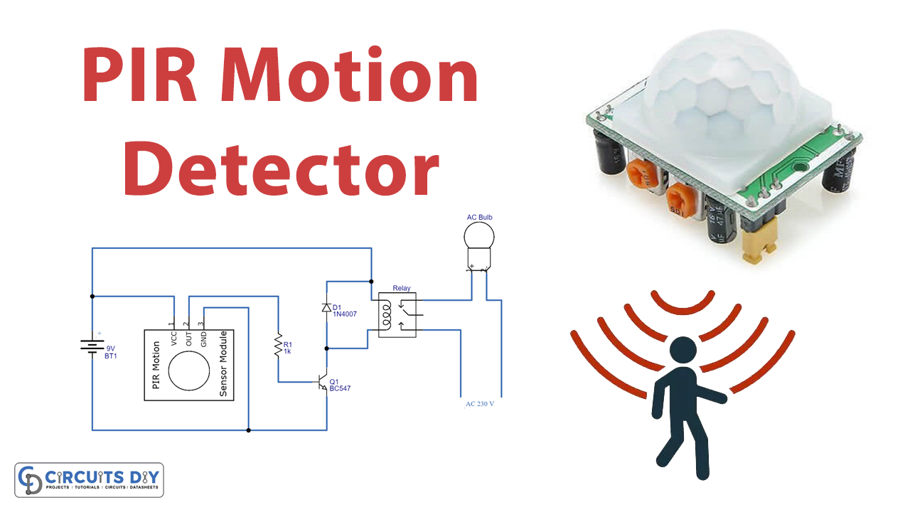
Circuit Diagram
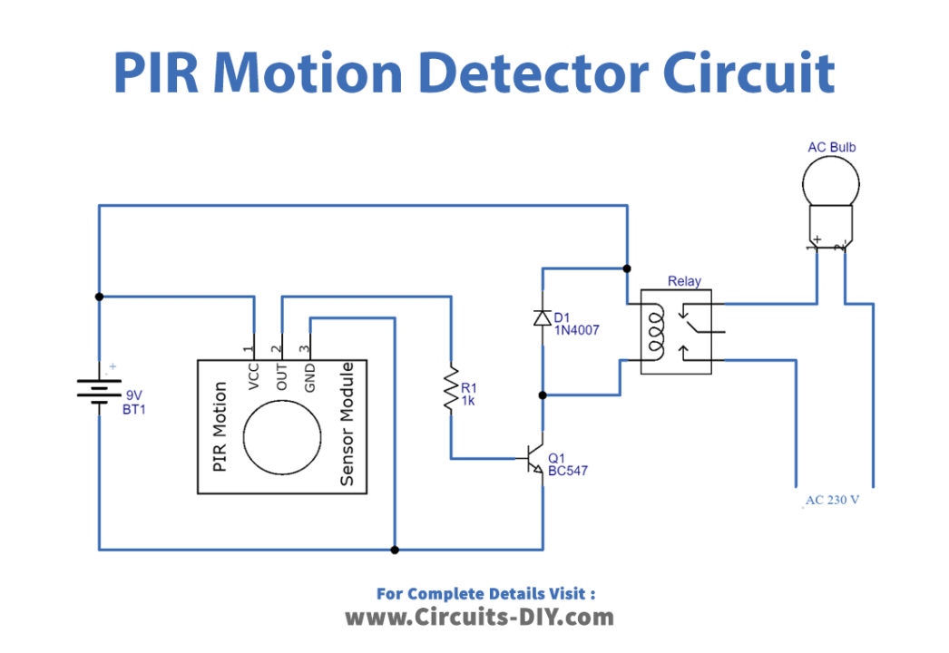
Working Explanation
As our circuit’s main part is the PIR sensor, it has only three terminals and gives a logical output when detecting the motion. Here as we know that every object emits some amount of infrared when heated. Human also emits infrared because of body heat. PIR sensors can detect a small amount of variation in infrared. Whenever an object passes through the sensor range, it produces infrared because of the friction between air and object and gets caught by PIR. Hence it can be used in stand-alone alarms, security circuits, or light automation circuits.
Now the PIR sensor’s output pin is connected to the switching transistor BC547 base and the relay coil is connected to the switching transistor collector terminal another end of the relay coil is connected to the positive supply, the electric bulb is connected with N/O (Normally Open) terminal. When a signal from an Infrared PIR sensor module comes to the circuit. Then, this signal flows to the base of Q1 through the R1-current limiting resistor for the transistor. Now as Q1 activates the current start flowing through a relay coil. When the relay turns On then the common pin makes contact with the N/O pin and the bulb starts to glow. A high volt AC supply is dangerous and must be handled with extreme care.
Applications
- This circuit can be implemented anywhere like a staircase or front gate etc.,
- One common application is activating automatic door openers in businesses and public buildings.
- Used in streets and indoors, activating street lights or indoor lights in walkways, such as lobbies and staircases.
- Such a detector may also trigger a security camera to record the possible intrusion.