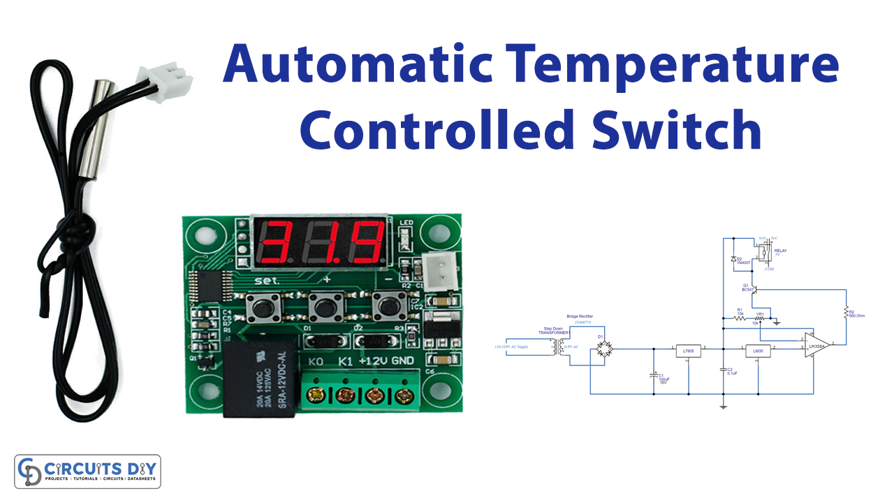
In this tutorial, we are going to make an “Automatic Temperature Controlled Switch”.
Sometimes we face situations, where we need to control home AC appliances according to temperature. In this kind of situation, we have to deal with temperature-dependent output or temperature-controlled output. So doing this work manually is quite difficult and risky. Hence, we design a circuit to detect the temperature by using sensor LM35, a relay switch, and a few affordable components. The following circuit makes changes automatically by turning ON and OFF the target electrical load or appliances. Once we tune the sensitivity level of temperature used in this circuit, it becomes an automatic temperature-controlled switch.
Hardware Components
The following components are required to make Temperature Controlled Switch Circuit
| S.no | Component | Value | Qty |
|---|---|---|---|
| 1. | Step-Down Transformer | 0-9V AC | 1 |
| 2. | Diode | 1N4007 | 5 |
| 3. | IC | LM7805 | 1 |
| 4. | Transistor | BC547 | 1 |
| 5. | Resistor | 10KΩ, 560Ω | 1,1 |
| 6. | Capacitor | 100uF/16V, 0.1uF | 1,1 |
| 7. | Temperature Sensor | LM35 | 1 |
| 8. | IC | LM358 | 1 |
| 9. | Variable Resistor | 10KΩ | 1 |
| 10. | Connecting Wires | – | – |
| 11 | Relay | 5V | 1 |
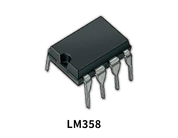
LM358 Pinout

For a detailed description of pinout, dimension features, and specifications download the datasheet of LM358
LM35 Pinout

For a detailed description of pinout, dimension features, and specifications download the datasheet of LM35
Temperature Controlled Switch Circuit
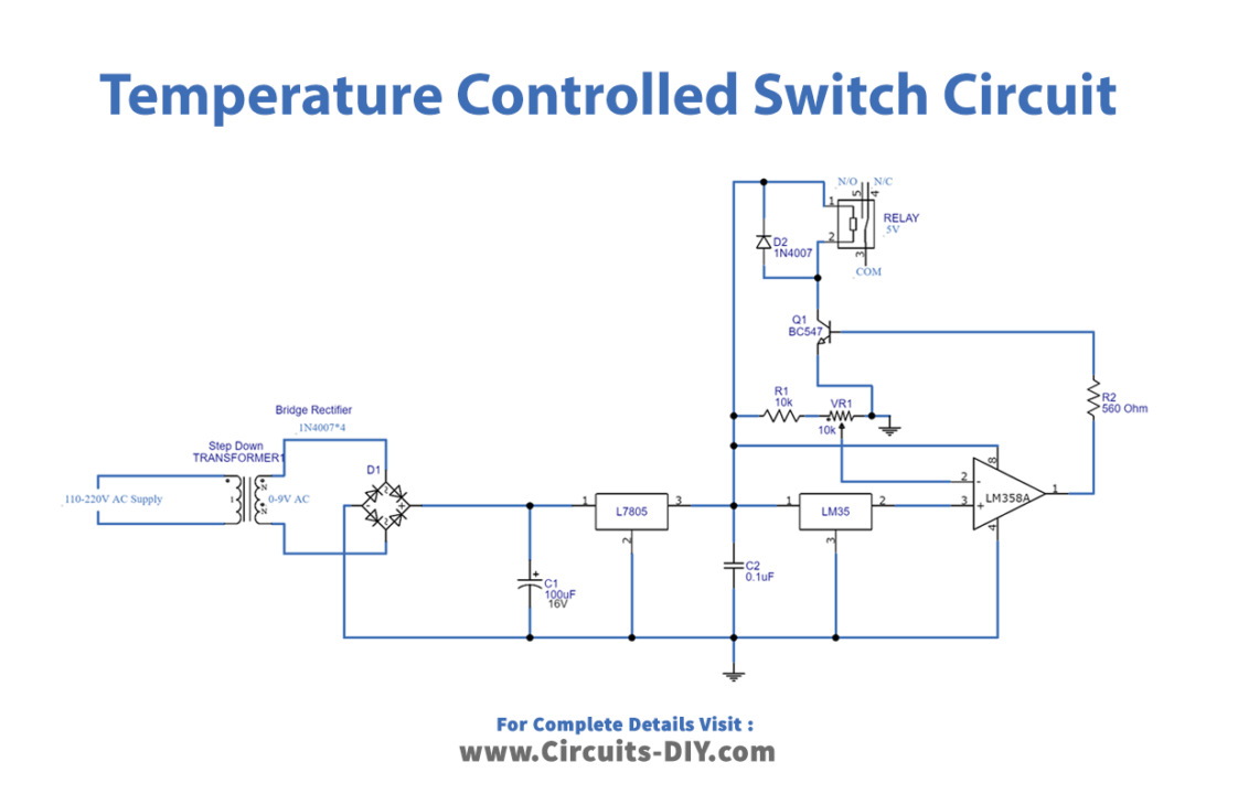
Working Explanation
As we can see this circuit starts with a rectifier and regulator unit, in which with the help of a step-down transformer high voltage AC (110 – 220V) supply is reduced to 9V AC. And then rectified into DC through a bridge rectifier. To eliminate AC ripples from rectified DC it goes through a filter capacitor, here C1 reacts as a filter then linear regulator IC 7805 regulates DC voltage and gives a constant 5V DC supply.
Temperature sensor LM35 gives output voltage linearly proportional to the centigrade temperature and LM358 operational amplifier helps us to choose the temperature level through VR1 variable resistor, the output of this operational amplifier drives the Q1 transistor. And as we have to set the reference voltage low at Pin 2 of LM358, so now the voltage at pin 3 (non-inverting input) becomes higher than the voltage at pin 2 (inverting input) and the output of op-amp LM358 (PIN 1) becomes HIGH. The output of LM358 is connected to the base of NPN transistor Q1, so Q1 also becomes ON which triggers the Relay, and the bulb gets turned ON. The relay coil is connected between +5V and Q1 transistor collector terminal. Here relay is configured by using a small driver circuit which consists of a Q1 transistor, diode, and a resistor. Transistor is used to amplify the current so that full current can flow through the coil to fully energize it. The resistor is used to provide biasing to the transistor. And diode is used to prevent reverse current flow when the transistor is switched OFF. Every inductor coil produces equal and opposite EMF when switched OFF suddenly, this may cause permanent damage to components, so a diode must be used to prevent reverse current. Now when the output is higher than 2.5V from the operational amplifier Q1 transistor turns ON and connects the relay coil to the Ground supply hence the coil gets energized and makes the N/O (normally open) contact with a closed one. By this circuit, we can control electrical load or appliances automatically depending on temperature, and handle it with extreme care and protection because it is involved in the operation of High voltage or AC.
Applications
This temperature-controlled circuit can be used in homes and offices, to detect the electrical load requirement and relay switches ON and OFF according to needs.