Introduction
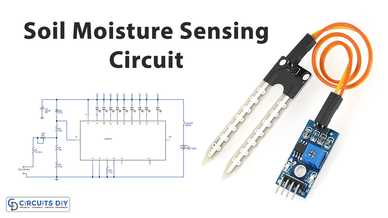
Moisture is an immense complication for agriculturalists and farmers. Unreasonable moisture can cause adverse effects on the soil. Thus, it reduces yield and also lends a pessimistic result as seed loss. It risks crops and plants. Also, it affects the irrigation system, Therefore, to prevent subtle moisture problems, the designers made a small and portable soil moisture sensor. The sensor estimates the volumetric content of the water and gives the reading accordingly. So, in this tutorial, we are going to “Soil Moisture Sensing Circuit”
Hardware Required
| S.no | Component | Value | Qty |
|---|---|---|---|
| 1. | IC | LM3915 | 1 |
| 2. | LED | – | 9 |
| 3. | Zener Diode | 2.7v | 1 |
| 4. | Potentiometer | 50KΩ | 1 |
| 5. | Switch | – | 1 |
| 6. | Capacitor | 100uF | 1 |
| 7. | Resistor | 75Ω, 2.2KΩ, 12KΩ, 5.6KΩ, 1.2KΩ | 1, 1, 1, 1, 1 |
| 8. | Test Probe | – | 1 |
| 9. | Battery | 9v | 1 |
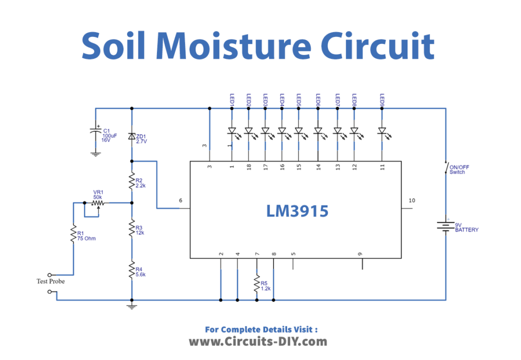
Circuit Diagram
Working Explanation
In this Soil Moisture Sensing Circuit, we are using the LM3915 IC which is connected with a 9V battery. We connected ten LEDs to the output terminals. To examine the different levels of output, use different colors of LEDs. We connected the test probe between divider resistors R3 and R2 through potentiometer VR1 and resistor R1. The probe makes the ground to the reference voltage at the pin6 of an IC and changes the reference voltage. Hence this depends on the reference voltage. For the probe, use slew less single-strand wire of copper as the test probe which can measure the moisture level in the soil. Put the test probe ground pin close to the test probe pin.
Application and Uses
- Agriculture.
- Irrigation systems.
- Farming devices, etc