Introduction
Music enthusiasts and audiophiles alike, are you ready to take your sound experience to the next level? Look no further as we bring you two circuit designs that promise to revolutionize your listening experience! These universal preamplifier and single-chip preamplifier circuits are designed to deliver superior sound quality and versatility, making them ideal for standard preamp applications. So, let’s dive in and explore the magic behind these great audio amplifiers!
The Universal Preamplifier Circuit is designed to work as a versatile preamplifier that can handle a wide range of input signals by adjusting the value of R1. On the other hand, the Single Chip Preamplifier Circuit uses an LM3900 IC comprising four Norton op amps to create a high-quality stereo preamp.
Hardware Required
You will require the following hardware for Simple Preamplifier Circuits.
Figure 1 Circuit Table
| S.no | Components | Value | QTY |
|---|---|---|---|
| 1 | Polar Capacitor | 10u, 100u | 1, 1 |
| 2 | Non Polar Capacitor | 82p | 1 |
| 3 | Resistor | 510k, 47k, 75k, 1k5, 1k2, 4k7, 270, 470 | 1, 1, 1, 1, 1, 1, 1, 1 |
| 4 | Transistor | MPS6515, 2N3906 | 1, 2 |
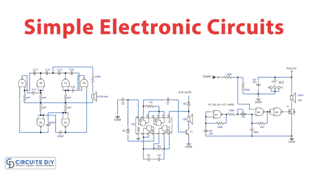
Circuit Diagram
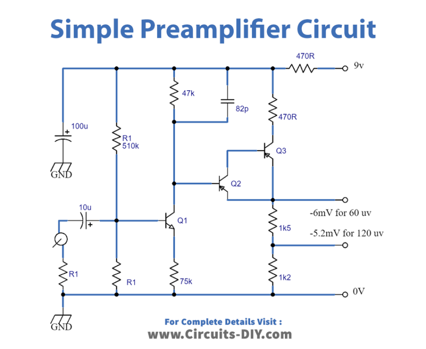
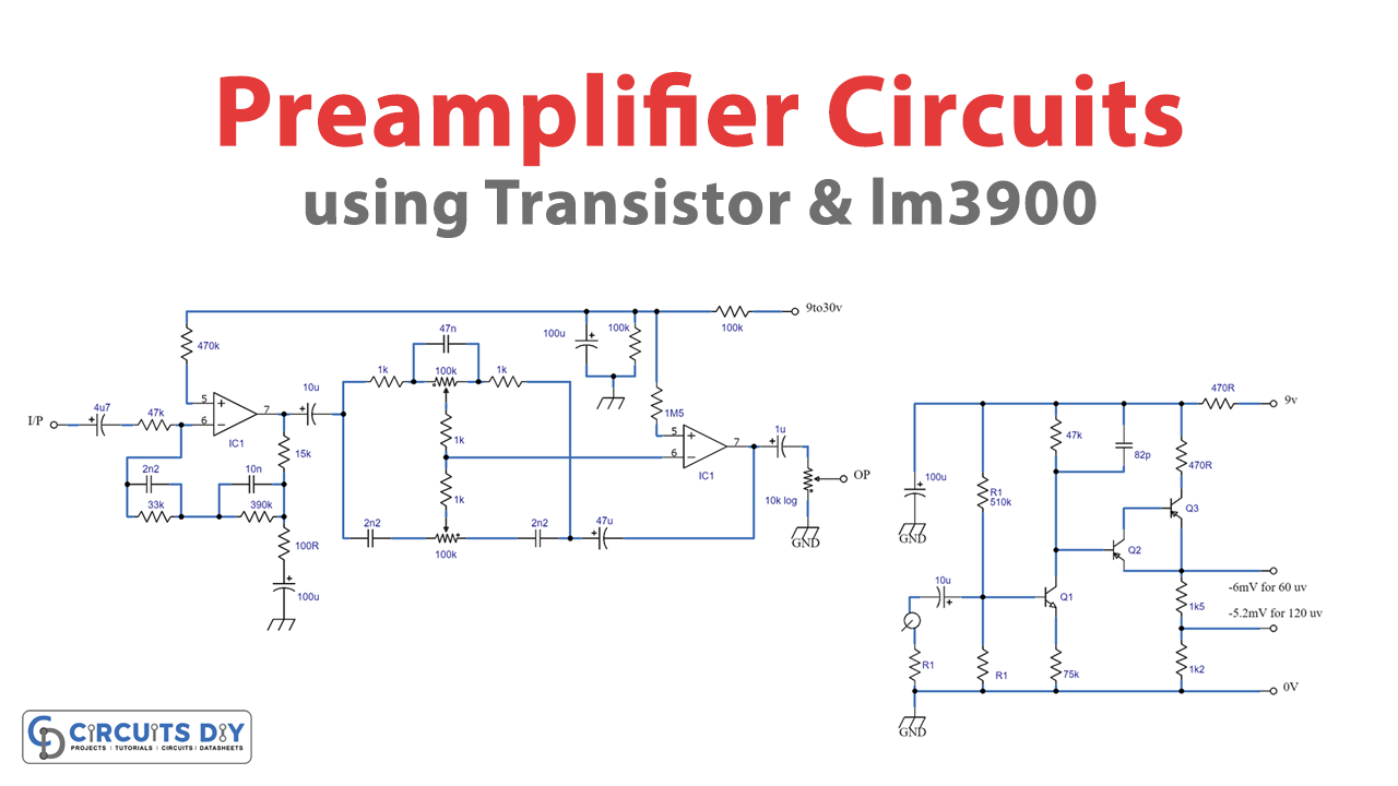
Figure 2 Circuit Table
| Components | Value | QTY |
| IC | IC1, IC2 LM3900 | 1, 1 |
| Polar Capacitor | 4u7, 10u, 47u, 100u, | 2, 2, 1, 2 |
| Non Polar Capacitor | 2n2, 10n, 47n | 3, 1, 1 |
| Resistor | 47k, 470k, 33k, 390k, 100r, 15k, 10k, 5k6, 1M5, 100k | 1, 1, 2, 1, 1, 1, 2, 1, 1, 2 |
| Variable Resistor | 10k, 100k | 1, 2 |
Circuit Diagram

Working Explanation
Universal Pre Amplifier Circuit
The Universal Preamplifier Circuit combines the input signals to the base of Q1 through the isolating capacitor C1. R1 is used to lower the input impedance to match the signal coming in. R2 and R3 are used to bias Q1. The amplifier’s output stage is a pair of Darlington transistors (Q2 and Q3). And the signals are taken from around R7 and R8. The value of R1 can be determined through experiments and is generally identified using a 470R preset in the R1 placement, which you can adjust for the best possible audio quality.
Single Chip Preamplifier Circuit
The Single Chip Preamplifier Circuit uses IC1 in the inverting mode. The input signals are fed through the blocking capacitor and R1 to the inverting input. R5 and R6 determine the mid-band gain of the stage, while the network (R3, R4, C2, and C3) provides the necessary RIAA equalization. The equalized signal is then fed to a common Baxendall tone control network built around IC2. This circuit uses individual volume controls for each channel, which minimizes crosstalk between channels and is more affordable. The efficiency of this circuit is decent, with a general distortion of less than 0.1% and a signal-to-noise (S/N )ratio of -67dB without a load, ref 500 mV out.
Final Words
In conclusion, the Universal Preamplifier Circuit and the Single Chip Preamplifier Circuit are two different preamplifier circuits that can be used for different applications. The Universal Preamplifier Circuit is versatile and can handle a wide range of input signals. At the same time, the Single Chip Preamplifier Circuit uses a single IC to create a high-quality stereo preamp with decent efficiency. Both circuits have unique features and can be used depending on the application’s specific requirements. Try those circuits, and ask away any questions you have in the comment section.