Introduction
Have you ever missed an important phone call because you were in another room or couldn’t hear the ringtone? The phone repeater circuit can solve this problem by expanding the range of your landline telephone ring sound. This circuit lets you hear your phone ring from another room or house.
The circuit extracts the signal directly from the telephone lines and amplifies it using transistors and a relay. Additionally, the circuit can be connected to a buzzer or warning light for those with hearing impairments. This simple yet effective circuit can be a lifesaver for those who don’t want to miss important calls and want to stay connected at all times.
Hardware Required
| S.no | Components | Value | Qty |
|---|---|---|---|
| 1 | Transistor | Q1, Q2: BC547B Q3: BC337 | 2 1 |
| 2 | Capacitor | C1: 0.033uF | 1 |
| 3 | Resistor | R1, R2: 100K R3: 8.2K R4: 180K R5: 39K | 2 1 1 1 |
| 4 | Buzzer | 12V | 1 |
| 5 | Diode | 1N4148 | 1 |
| 6 | Polar Capacitor | C2: 1uF, 50V | 1, 1 |
| 7 | Relay | 12V | 1 |
Do not reverse the polarity of the telephone wires to the repeater.
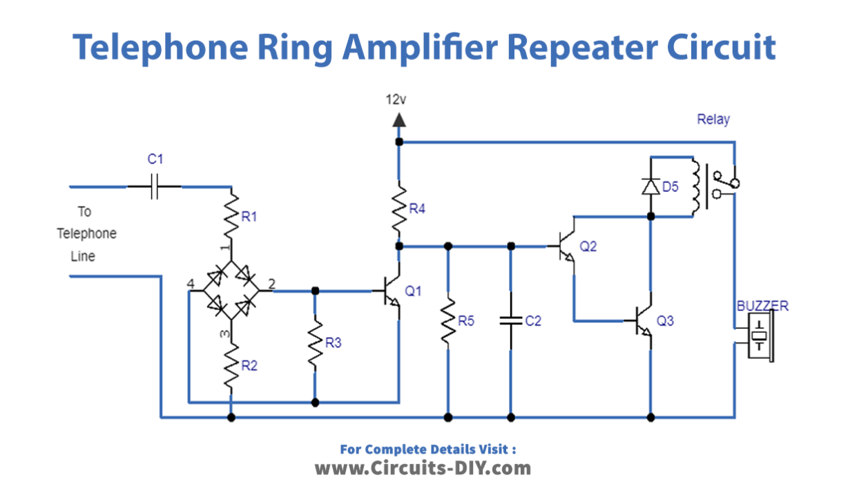
Circuit Diagram
Circuit Working:
Step 1: Signal Extraction
The first step in the circuit is to extract the signal directly from the telephone lines. The current from the lines goes through capacitors C1 and resistors R1, R2, R3, and a rectifier bridge made by diodes D1, D2, D3, and D4. This results in a filtered DC signal. That is then applied to the base of transistor Q1 through a positive pulse signal.
Step 2: Transistor Q1 Action
Transistor Q1 responds to the rhythmic pattern of the signal received at its base, which results in an inverted and amplified signal across its collector resistor. This amplified collector signal is then restricted by the resistor R5 and capacitor C2 network to ensure that the signal is not pulsed but direct and straight.
Step 3: Transistor Q2 and Q3 Amplification
The modified DC signal is then used on the set of Q2 and Q3 transistors associated in the Darlington configuration for further amplification to ensure the final output is ready to actuate the relay to turn on the buzzer.
Step 4: Protection for Transistors Q2 and Q3
D5 is used to preserve transistors Q2 and Q3 for reverse relay coil back EMFs.
Step 5: Output
The final output of the circuit is used to actuate the relay to turn on the buzzer or warning light (optional).
Final Words
In conclusion, the phone repeater circuit we discussed is
an excellent solution for increasing their landline telephone ring sound range. This circuit can be easily constructed using commonly available components and provides a reliable way to stay connected and not miss important calls.
We hope you found this explanation helpful and informative. If you have any questions or queries regarding the circuit or its implementation, please feel free to leave a comment. We would be happy to assist you in any way possible.