Introduction
Bring a touch of nostalgia to your electronic projects with this tutorial on building a simple 220V ding-dong bell circuit. We’ll take you through the step-by-step process of creating a circuit that not only adds a fun and unique sound to your projects but also evokes memories of the classic Ding dong bell. Whether you’re a beginner just starting out with electronics or an experienced maker looking for new challenges, this tutorial is sure to be a hit.
So, let’s get started and discover the magic of creating your own ding-dong bell circuit!
Hardware Required
You will require the following hardware for Ding Dong Bell Circuit.
| S.no | Component | Value | Qty |
|---|---|---|---|
| 1. | IC | HT2611 | 1 |
| 2. | Transformer | 4.5V | 1 |
| 3. | Bridge Rectifier | – | 1 |
| 4. | Capacitor | 2.2, 4.8, 100, 2200uF | 1, 1, 1, 1 |
| 5. | Resistor | 1k, 100R, 100k, 220k, 330k, 680k | 1, 1, 1, 1, 1, 1 |
| 6. | Transistor | BC548, BC327 | 1, 1 |
| 7. | Diode | 1N4007 | 2 |
| 8. | Zener | 3.3v | 1 |
| 9. | Speaker | – | 1 |
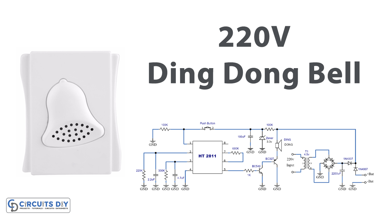
Circuit Diagram

Working Explanation
The circuit includes two parts:
Power Supply Circuit
The power supply part of the circuit derives its voltage from the house’s electrical network to power the equipment. It also enables the system to be powered by batteries in the event of a power outage. The transformer reduces the voltage to 4.5v AC. The rectifier bridge (PR) changes alternating current into DC, filtered by the 2200μF capacitor. The 1N4007 diodes act as a source selector, enabling the system to work with mains or batteries as needed. The fuse protects the 220v portion of the transformer. The rectifying bridge (PR) can be any device with a voltage over 250V and a current of less than 1A. The + V point represents the output of the supply, while the batteries (4 in series) connect across the + Bat and -Bat points.
Main Ding Dong Bell Circuit
The circuit receives power from the terminals marked V+ and ground. The main component of it is the integrated HT2811. Pin 1 generates the clock signals, enabling the chip to create the “Ding-Dong” audio. Pins 2 and 3 are associated with RC sets that determine the two tones of the sounds (2 = “Ding” / 3 = “Dong”). These elements can be modified to change the sound quality of the bell.
Pin 4 refers to the volume. Pin 5 outputs the sound signal, which is amplified by a pair of general-purpose transistors in a Darlington setup. Terminals 6 and 7 are connected to a 680K resistor, which modifies the gain of the chip’s internal preamplifier. Finally, terminal 8 powers the chip, which is current-limited by the 100-ohm resistance and stabilized to 3.3v by the zener diode. The 100μF capacitor filters any residual ripple in the supply line.
The power supply provides the circuit with the necessary voltage to operate. Now, when the bell is pressed, the “Ding-Dong” generator creates a weak audio signal with the sound of the bells. The signal is then amplified by the amplifier and played through the speaker.
Final Words
In this tutorial, we have covered the process of building a simple 220V ding-dong bell circuit, including the materials needed, step-by-step instructions, and key concepts to keep in mind. We hope you have found this tutorial informative and easy to follow.
With the knowledge and skills you have gained from this tutorial, you can now create your own ding-dong bell circuit and add a touch of nostalgia to your electronic projects. We encourage you to experiment with different variations of the circuit and to continue exploring the world of electronics and sound-making.