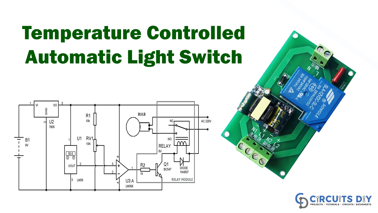
Again with the aid of this tutorial, we show you the construction of Temperature Controlled Automatic Switch. So, we improve the circuit with a switch, and now we go to Home Control AC devices with temperature control. This circuit is used as an electronic light switch to operate if the temperature goes above a certain threshold (50° C). As just a temperature probe, we use LM35 here. By changing the circuit’s voltage divider according to the requirement, you can alter this 50 ° C threshold.
In this temperature-controlled circuit, we use a simple LED bulb to illustrate. If the temperature reaches 50°C, then the bulb is turned on automated, and if the level rose 50°C, the bulb is automatically shut off. Any domestic AC system can replace the bulb here.
Hardware Component
The required hardware components are
| S.no | Component | Value | Qty |
|---|---|---|---|
| 1. | Op-amp | LM358 | 1 |
| 2. | LED (optional) | – | 1 |
| 3. | Transistor | BC547 | 1 |
| 4. | Relay | 6v | 1 |
| 5. | Resistor | 1K, 10K, 10K Var | 1, 1, 1 |
| 6. | Temperature sensor | LM35 | 1 |
| 7. | IC | 7805 | 1 |
| 8. | Battery | 9v | 1 |
| 9. | Diode | 1N4007 | 1 |
| 10. | Bulb or any AC appliance | – | 1 |
LM358 Pinout

For a detailed description of pinout, dimension features, and specifications download the datasheet of LM358
7805 Pinout
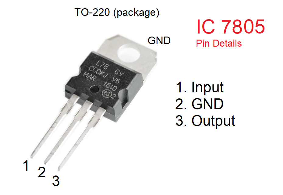
For a detailed description of pinout, dimension features, and specifications download the datasheet of 7805
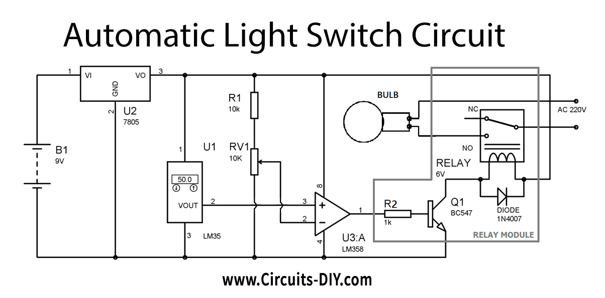
Temperature Controlled Automatic Switch Circuit
Circuit Operation
It is indeed easy to run this circuit with temperature-controlled household equipment. The 9v battery is used for the power-up of the entire circuit and IC7805 for the supply of 5v to the circuit regulated. If the temperature is much less than 50 ° C, LM358 output remains SOF, and transistor Q1 & Relay remains OFF.
As the temperature around is above 50 ° C, the LM35 output voltage at pin 2 also be about 0.5 volts or 500 mV. The LM35 output is connected to the LM358 Pin 3. Although the reference voltage set at Pin 2 (LM358 volt), the voltage set at Pin 3 (not inverted input) is more significant than Pin 2 (inverted input), and the LM358 (PIN 1) output is higher than the voltages at Pin 2 (inverted input). The LM358 output is also connected to the Inverting amplifier base Q1 so that Q1 is ON to cause the stimulation and switch the bulb ON. However, this is considered controversial because the maximum temperature switches on the app automatically.
Applications and Uses
In some instances, the thermal analysis output or temperature-controlled output is required and is automatically produced by the following circuit. Temperature sensor LM35 for this circuit is being used to detect the electrical load requirement and relay switches ON and OFF