Overview
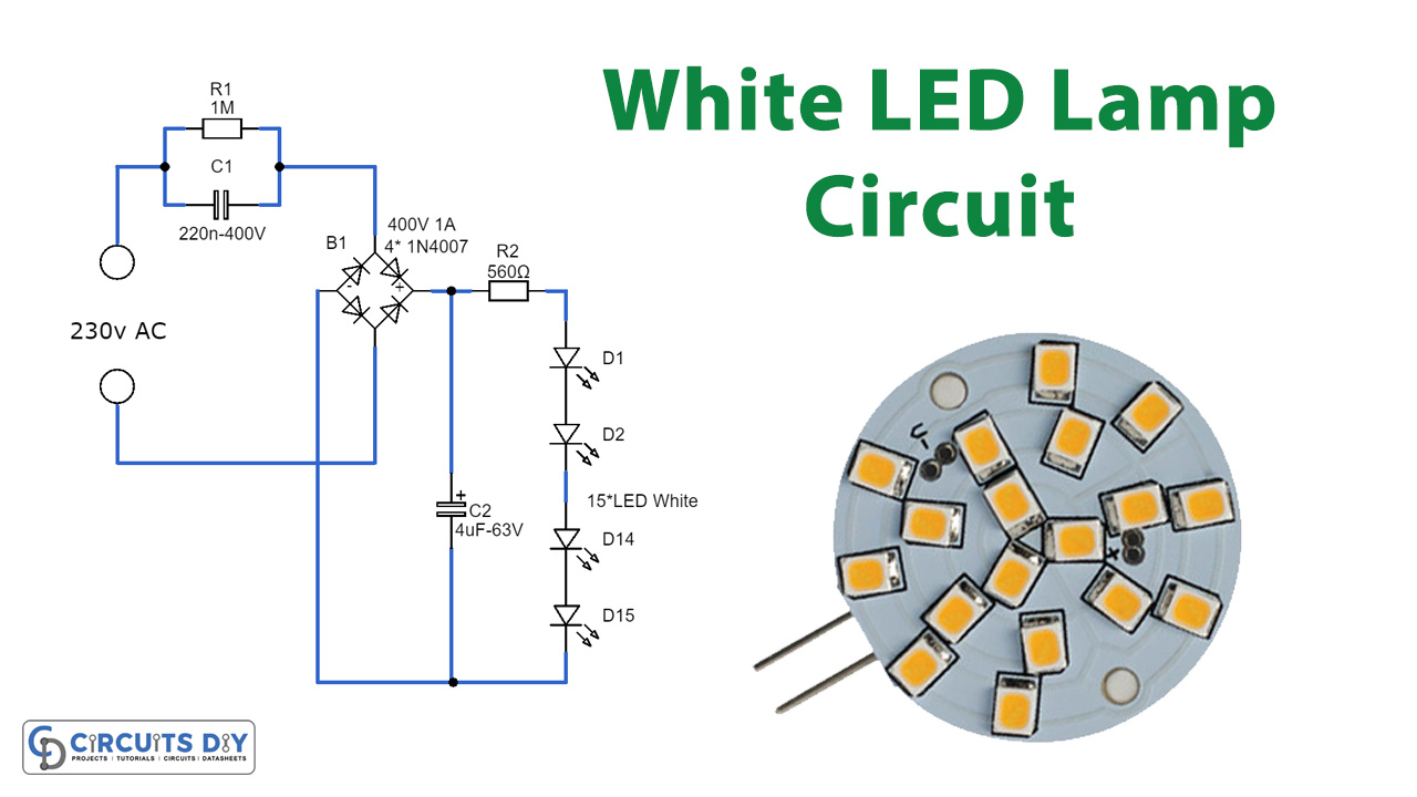
Have you ever thought about using an array of white LEDs as a compact lamp for your living room? If not, let me explain. Ready-made LED lamps are available that look just like standard halogen lamps and can be installed in a standard 230-V light fixture. We took one apart, and unsurprisingly, it uses a capacitor to reduce the voltage from 230 V to a level suitable for the LEDs. This approach is more cost-effective and compact compared to using a transformer. The lamp consumes only 1 watt, resulting in less brightness than a 20 W halogen lamp. The light also has a slightly bluer hue. Here’s how the circuit works: C1 acts as a voltage-dropping “resistor,” ensuring that the current stays within a safe range (around 12 mA).
Hardware Components
To make White LED Lamp Circuit, you’ll need the following hardware components to get started:
| S.no | Components | Value | Qty |
|---|---|---|---|
| 3 | Polar Capacitors | C1 = 220n 400V C2 = 4µ7 63V | 1 1 |
| 4 | Diodes | 400V 1A = 4*1N4007 | 4 |
| 5 | Resistors | R1 = 1M R2 = 560Ω | 1 1 |
| 6 | LEDs | D1 ,D2 ,D14 ,D15 = 15* LED white | 4 |
Schematic
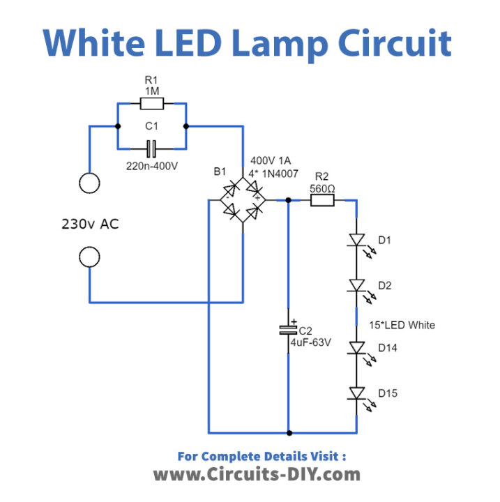
The bridge rectifier plays a crucial role in converting the incoming AC voltage into DC voltage, which is essential for the proper functioning of LEDs as they can only operate on DC voltage. It’s important to note that LEDs are sensitive and can fail if exposed to negative voltages exceeding 5 V.
The electrolytic capacitor serves a dual purpose in this circuit. Firstly, it ensures that there is a steady voltage supply to illuminate the LEDs even when the mains voltage drops below the forward voltage required by the LEDs. Secondly, it handles the inrush current peak that occurs when the mains power is switched on, preventing potential damage to the LEDs caused by sudden current spikes.
Additionally, the 560-ohm resistor plays a key role in maintaining a more consistent current flow through the LEDs, resulting in a more uniform and stable light output. This resistor helps regulate the current, ensuring that the LEDs receive the right amount of power and enhancing their overall performance.
The 560-ohm resistor experiences a voltage drop of approximately 6.7 V, allowing a safe current of 12 mA to flow through the LEDs. The total voltage drop across the LEDs, considering 15 LEDs with a voltage drop of 3 V each, sums up to around 45 V. Meanwhile, the voltage across the electrolytic capacitor measures slightly over 52 V.
To understand the functionality of C1, we can calculate its impedance (AC voltage resistance) using the formula 1/(2π·f·C), where f represents the frequency and C denotes the capacitance. In this case, the impedance calculation is 1/ (2·3.14·50·220·10-9), resulting in approximately 14.4 kΩ. Multiplying this impedance by the current of 12 mA yields a voltage drop across the capacitor of about 173 V.
This setup aligns well because the 173-V capacitor voltage combined with the 52-V LED voltage totals 225 V, which is sufficiently close to the official mains voltage of 230 V. This configuration ensures stable and efficient operation within the specified voltage parameters.