In this project tutorial, we are going to show you an automatic solar garden light utilizing a 555 timer and other discrete segments. For individuals who have a fascination with gardening, a garden light would give admirable beauty to their plants in any event, during the evening time.
These lights will ordinarily be set inside the garden, a long way from electrical outlets since it’s not a smart thought to run wires through your garden soil which will be wet most of the time. This is the place where Solar-power garden lights come into the image. These lights will have a battery that will charge through a sunlight-based board in the daytime and during the evening time, the power from the battery is utilized to control the lights, and the cycle rehashes.

Hardware Components
The following components are required to make an Automatic Solar Garden Light Circuit
| S.no | Components | Value | Qty |
|---|---|---|---|
| 1. | IC | NE555 timer | 1 |
| 2. | Solar Panel | 9V 3W | 1 |
| 3. | Resistor | 1K, 8.2K, 10K, 470R, 2.2K, 390Ω | 2, 1, 1, 1, 1, 12 |
| 4. | Ceramic Capacitor | 10nF | 1 |
| 5. | Potentiometer | 100K | 1 |
| 6. | Battery | 6V | 1 |
| 7. | Diode | 1N5822, 1N4148 | 1, 3 |
| 8. | Transistor | BD140 | 1 |
| 9. | Transistor | 2N3906 | 1 |
| 10. | Zener Diode | 3.3V | 1 |
| 11. | Relay | 6V | 1 |
| 12. | LEDs | – | 13 |
| 13. | Optocoupler | PC817 | 1 |
NE555 IC Pinout

For a detailed description of pinout, dimension features, and specifications download the datasheet of 555 Timer
2N3906 Pinout
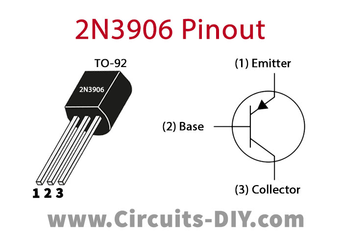
For a detailed description of pinout, dimension features, and specifications download the datasheet of 2N3906
Automatic Solar Garden Light Circuit

Working Explanation
The circuit is additionally utilizing 12 white LEDs of 20mA. The circuit can run these LEDs for as long as 10 hours at full brightness. A 6V 4AH or 4.5AH lead-acid battery is utilized here which will charge in the first part of the day and in night, it will give the capacity to the 12 LEDs. The circuit likewise comprises an automatic charging system for charging this 6V battery that will consequently cut off the battery from the solar panel when it turns out to be completely energized. This will spare the battery from overcharging and subsequently increase the battery life. The LED associated with the 470 ohms resistor will illuminate when the battery is completely energized.
After the circuit is finished fabrication it requires a few adjustments for the first time. For that reason, you will require a variable power supply. Presently, the power supply is set at 7.3 volts. Then expel the 6V battery from the circuit associate the variable power supply and adjust the 100K pot until the fully energized pointer LED lights. After this setting, the circuit will be prepared for utilization.
Applications and Uses
From the title of this project, this is clear that this project is used as a garden light that is fueled by solar energy.