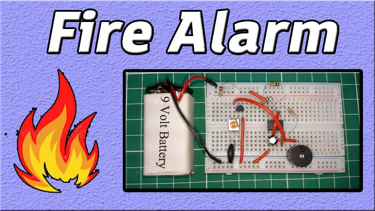
Fire Alarm Circuits are very important devices to detect fire at the right time and prevent any damage to people or property. Fire Alarm circuits are mostly used in industries, homes, cinemas, fuel stations & shopping malls to detect fire accidents. The fire alarm circuit actually gives an alarming signal when the temperature exceeds a certain amount of threshold. Today in this tutorial we are going to make a “Fire Alarm Circuit using 555 Timer“. For a better understanding of making this circuit please watch this video.
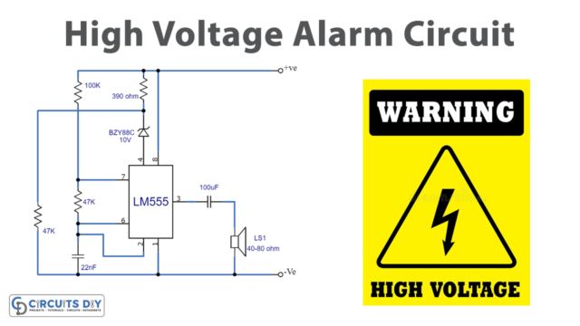
The heart of this Fire alarm circuit is a 555 Timer IC. The IC possesses an oscillation frequency ranging from 670 to 680 Hz. Here, this NE555 timer acts as an astable multivibrator An astable multivibrator is a free-running oscillator that switches continuously between its two unstable states. With no external signal applied, the transistors alternately switch from cutoff to saturation state at a frequency that RC time constants of the coupling circuit determine. If these time constants are equal (R and C are equal) then a square wave will generate with a frequency of 1/1.4 RxC. Hence, an astable multivibrator is also a pulse generator or a square wave generator.
Hardware Components
The following components are required to make a Fire Alarm Circuit
| S. No | Component | Value | Qty |
|---|---|---|---|
| 1. | IC | 555 Timer | 1 |
| 2. | NPN Transistor | BC547 | 1 |
| 3. | Thermistor NTC | 10K | 1 |
| 4. | Resistors | 1K, 100K, 4.7K | 1, 2, 1 |
| 5. | Variable Resistor | 1M | 1 |
| 6. | Capacitor | 10uF | 1 |
| 7. | Buzzer | – | 1 |
| 8. | Battery | 9v | 1 |
| 9. | Breadboard | – | 1 |
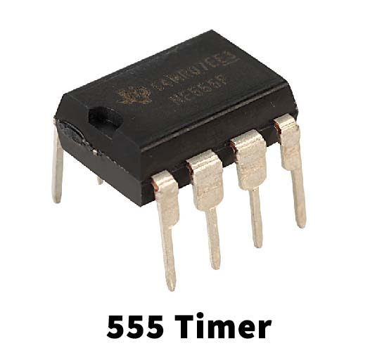
555 Timer Pinout

For a detailed description of pinout, dimension features, and specifications download the datasheet of 555 Timer IC
Fire Alarm Circuit
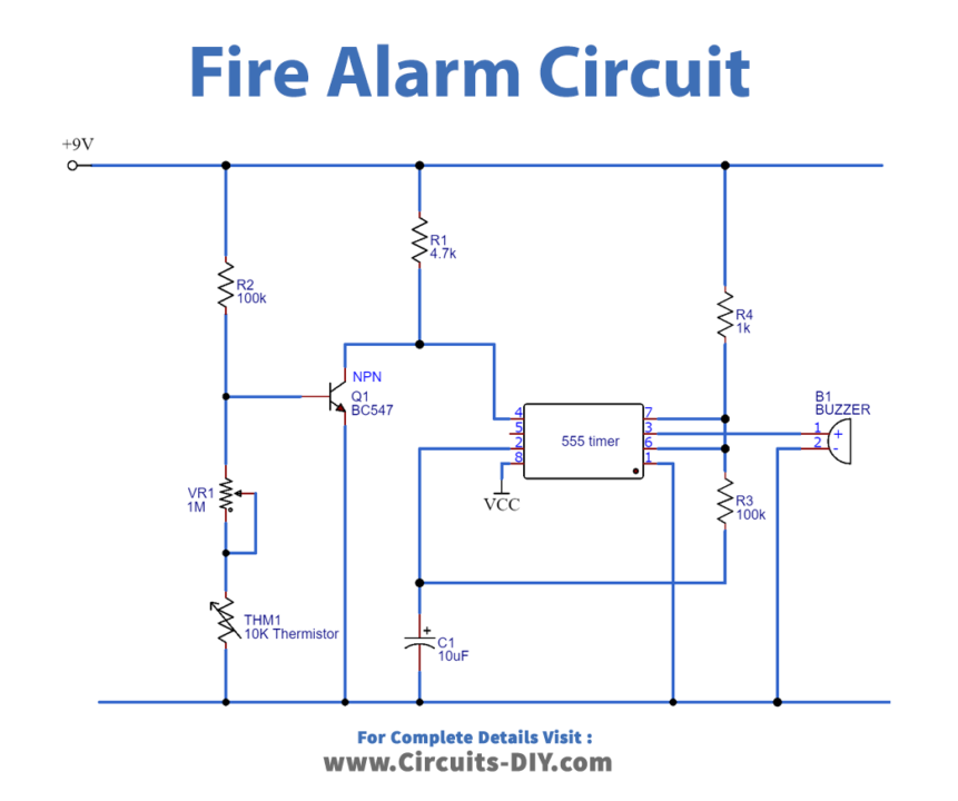
Working Explanation
When there is no heating element, the thermistor remains at 10k ohm. At this point, the transistor remains at an ON state because there is sufficient voltage across the base-emitter of the transistor, which keeps it ON. When the transistor is ON, Pin 4 (RESET) is connected to the ground, and when the Reset pin is at the Ground, the IC doesn’t operate.
Now when we apply heat to the Thermistor through a fire source, its resistance starts to decrease, and when its resistance decreases, the voltage at the base of the Transistor starts to decrease and when the voltage becomes less than the operating voltage of the transistor, then transistor turns OFF. And the Reset pin of the 555 timer IC, gets positive voltage through R3, the 555 IC starts to work, and the buzzer beeps.
Applications
- Fire detection and alarm systems play an important role in industrial fire protection in order to ensure & sustain human life.
- A mandatory part of modern commercial & residential areas.