Introduction
High-voltage alarm circuits are essential in ensuring electrical systems’ safety. They serve as an early warning system, alerting technicians and operators to potential dangers before they can cause severe damage or injury. These circuits are designed to detect and respond to high voltage levels, automatically shutting down power to the affected area to prevent further damage.
Not only do high-voltage alarm circuits help keep workers and equipment safe and play a crucial role in protecting the power grid from costly power outages. The early detection and response provided by these circuits can minimize downtime and reduce the overall cost of repairs and maintenance. With their advanced features and reliable performance, high-voltage alarm circuits are a must-have for any facility or system that relies on electricity. So, why not try to make that circuit?
Hardware Required
You will require the following hardware for High Voltage Alarm Circuit.
| S.no | Component | Value | Qty |
|---|---|---|---|
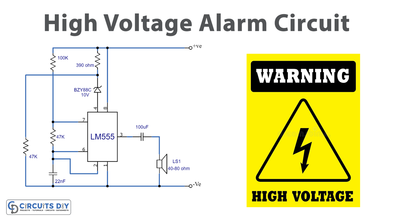
| 1. | IC | NE555 Timer | 1 |
| 2. | Capacitor | 22nF, 25uF | 1, 1 |
| 3. | Resistor | 390, 2.2, 4.7, 100k | 1, 1, 1, 1 |
| 4. | Diode | BZY88C | 1 |
| 5. | Speaker | 40-80 OHM | 1 |
Circuit Diagram

Construction
Due to the lack of available space on the standard boards, the high-voltage alarm circuit must be housed in a separate piece of equipment. This is necessary since the common boards cannot accommodate the circuit in its entirety. As a result, the components are stored separately in their respective boxes, and a 3.5mm jack socket is used to connect them. This jack plug is the one that is connected to a jack socket so that the mains electricity may flow through it.
Working Explanation
An alarm circuit is a device that sounds an alarm when a specific condition is met. In this case, the situation is that a particular voltage level must be reached across a component called D1. When the voltage level is reached, D1 becomes highly biased, allowing electricity to flow through it. This flow of electricity then passes through other components in the circuit, R3, R4, and D1, and creates a potential difference of 0.5 volts across R4. This potential difference is enough to trigger the alarm and make it ring.
The threshold voltage, or the level at which D1 becomes biased and allows electricity to flow through the circuit, can be adjusted by changing the voltage applied to D1.
However, it’s important to note that the circuit should not be exposed to very high voltages, especially at the IC1 point. This is because high voltage can damage the circuit and make it unreliable. Also, if the voltage level at IC1 drops below 5.1 V, the circuit will not operate systematically. This means that the alarm may not ring when it is supposed to or stop ringing when it is supposed to. Therefore, it’s crucial to ensure that the circuit operates within its specified voltage range to ensure proper functionality.
Final Words
To sum up, constructing a High Voltage Alarm Circuit is a creative and satisfying activity. It takes a few simple tools and a small bit of expertise for anybody to build this circuit. Feel free to post any questions or issues you may have here, and we will do our best to answer them.