A Simple timer circuit is a crucial part of any electronic circuitry that introduces a set time delay in various switching devices. This delay of a few seconds or minutes becomes a crucial requirement for ensuring the correct operation of a circuit. Without the specified delay, introduced by this circuit, a device could malfunction or even get damaged. So, in this project, we are going to design a simple timer circuit using 3 2N3904 NPN Transistors.
2N3904 is an NPN transistor, hence the collector and emitter will remain open (Reverse bias) when the base pin is held at the ground and will be short (Forward bias) when a signal is provided to the base pin. 2N3904 has a gain value of 300. The maximum amount of current that could flow through the collector pin is 200mA. Hence, we cannot connect loads that consume more than 200mA using this transistor. In order to bias a transistor, we have to supply current to the base pin. This current (IB) should be limited to 5mA.
Hardware Components
The following components are required to make Timer Circuit
| S.no | Component | Value | Qty |
|---|---|---|---|
| 1. | Breadboard | – | 1 |
| 2. | Connecting Wires | – | 1 |
| 3. | Battery | 9v | 1 |
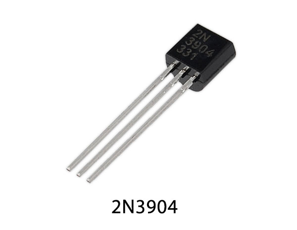
| 4. | Transistor | 2N3904 | 3 |
| 5. | Relay | – | 1 |
| 6. | Push-button | – | 1 |
| 7. | Diode | 1N4007 | 1 |
| 8. | IC | LM7805 | 1 |
| 9. | Capacitor | 470uF | 3 |
| 10. | Resistor | 470k, 47k | 3, 3 |
2N3904 Pinout
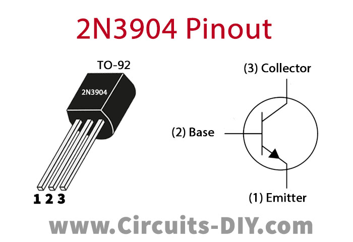
For a detailed description of pinout, dimension features, and specifications download the datasheet of 2N3904
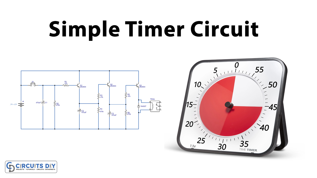
Timer Circuit
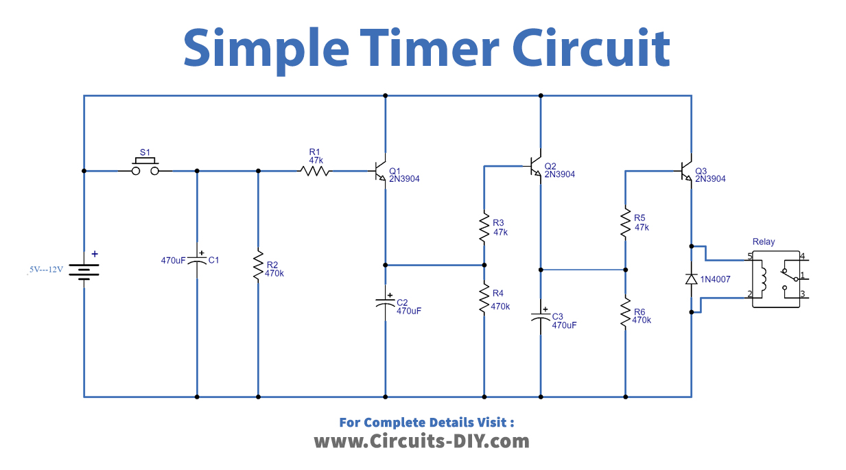
Working Explanation
This circuit is basically an enhanced version of a simple single transistor time delay circuit. On momentarily pressing the pushbutton (S1) the transistor Q1 receives a control signal at its base through a 47K resistor. this triggers the Q1 switch and charges capacitors C1 & C2.
Now, when the pushbutton is released disconnect the circuit from the power. The Capacitor C2 discharges after a delay & subsequently triggers transistor Q2, charging capacitor C3 which introduces a further delay. After this, the capacitor C3 discharges and triggers the transistor Q3. Subsequently which, the relay coil energizes & makes the SPDT switch, in order to power an AC or DC load.
Applications
- It commonly serves as a protection circuit to protect any electrical or electronic equipment and appliance from sudden high or unstable voltage such as voltage stabilizer for the fridge, UPS & PCs.