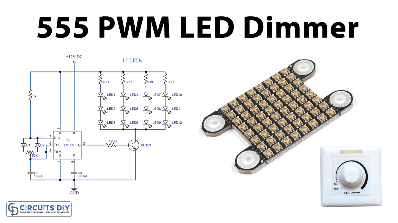
The 555 PWM LED dimmer circuit controls the brightness of the LEDs. The main concept of the circuit is to generate a pulse width modulation PWM signal with the help of a good old reliable 555 timer IC and to change the power supplied to the LEDs, thereby achieving the LED dimming effect. The circuit is designed around a popular 555 timer IC, which acts here as an astable multivibrator. It is one of the most famous ICs and is used in a wide range of applications such as a timer, oscillator, and generation of pulses.

Hardware Components
The following components are required to make LED Dimmer Circuit
| S.no | Component | Value | Qty |
|---|---|---|---|
| 1. | LEDs | – | 12 |
| 2. | IC | NE555 Timer | 1 |
| 3. | Resistor | 1K, 120, 68 ohms | 1,1,4 |
| 4. | Diode | 1N4007 | 2 |
| 5. | Capacitor | 100nF, 0.01uF | 1,1 |
| 6. | Transistor | BD139 | 1 |
| 7. | DC power supply | 12 volts | 1 |
| 8. | Potentiometer | 50K | 1 |
NE555 IC Pinout

For a detailed description of pinout, dimension features, and specifications download the datasheet of 555 Timer
LED Dimmer Circuit
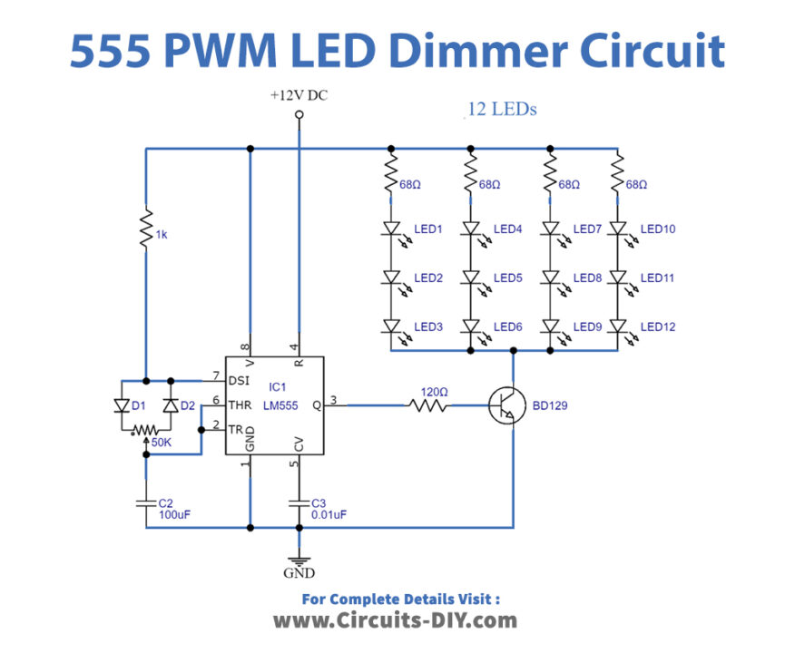
Working Explanation
The circuit is designed around a popular 555 timer IC whose nominal performance is 200mA due to which it can drive just a few LEDs, but for the IC performance, we use a BD139 transistor that could drive up to 1A current charge. The circuit uses 12 white LEDs which are super bright. If you choose to attach further LEDs only connect each of the three LEDs as shown in the circuit diagram with a 68-ohm resistor. The circuit can accommodate as many as 40 LEDs. The 50K variable resistor is used as needed to adjust the brightness of LEDs. A high current output resistor like TIP31, TIP41, etc may also be used for moving more than 1A current load or more LEDs.
Applications and Uses
- 555 PWM LED Dimmer circuit is used in street lights, lamps, etc.