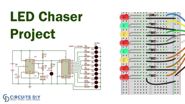
In this tutorial, we are making a project of a simple multiple-door open indicator circuit. This circuit is simple and its purpose is to monitor or detect if a door has been left open. We are using three normally closed reed switches, that are placed on desired doors. You can increase the number of reed switches if you want to monitor more doors. This circuit is capable of covering a large area which is one of its best qualities, so you can easily increase the length of the wire to increase the number of doors.
Hardware Components
The following components are required to make Door Indicator Circuit
| S.no | Component | Value | Qty |
|---|---|---|---|
| 1. | Input supply DC | 9-12V | 1 |
| 2. | Reed Switch | – | 3 |
| 3. | IC | NE555 Timer | 1 |
| 4. | Relay | 12V | 1 |
| 5. | Diode | 1N4007 | 1 |
| 6. | Resistor | 100KΩ | 1 |
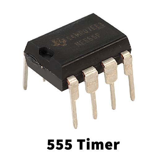
NE555 IC Pinout

For a detailed description of pinout, dimension features, and specifications download the datasheet of 555 Timer
Door Indicator Circuit

Working Explanation
The operating voltage of this circuit is 9 to 12 volts DC. This circuit is built around 555 timer IC. There are three normally closed reed switches so when a door is left open these switches will open and send a signal to the 555 timer IC. The IC will give a high output and activates the relay switch connected at its output. You can connect any AC or DC bulb for visual indication or any AC/DC alarm with it for example a doorbell so that you will be notified every time a door is left open.
This circuit can be operated at voltages below 9V but you will have to use the relay of the same voltage.
Applications and Uses
This circuit has a lot of applications for security purposes.