Introduction
Building your own Bicycle Light and Alarm Circuit is a fun and easy project that is perfect for beginners. Not only will you be able to customize your bike and make it stand out, but you will also be adding an extra layer of safety while cycling at night.
The circuit comprises a few simple components that can be easily obtained from an electronics store or online. Once you have the parts, all you need is a basic understanding of soldering and wiring. The included instructions will guide you step-by-step through the assembly process, making it easy for even a beginner to understand.
In no time, you will have a fully functioning Bicycle Light and Alarm Circuit that will make your bike look cool and make you feel safe while cycling in the dark. It’s a great way to learn about electronics and have fun at the same time. So, why wait? Gather your tools, grab the components, and let’s get started on building your own Bicycle Light and Alarm Circuit!
Hardware Required.
You will require the following hardware for Bicycle Light and Alarm Circuit.
| S.no | Component | Value | Qty |
|---|---|---|---|
| 1. | Capacitor | 100uF | 2 |
| 2. | Resistor | 4K7, 100K | 2, 1 |
| 3. | Transistor | BC141, BD241, BC547B | 1, 1, 2 |
| 4. | LED | 500, 50mA | 1, 5 |
| 5. | Battery | 6V | 1 |
| 6. | Fuse | 1.5A | 1 |
| 7. | Switch | – | 2 |
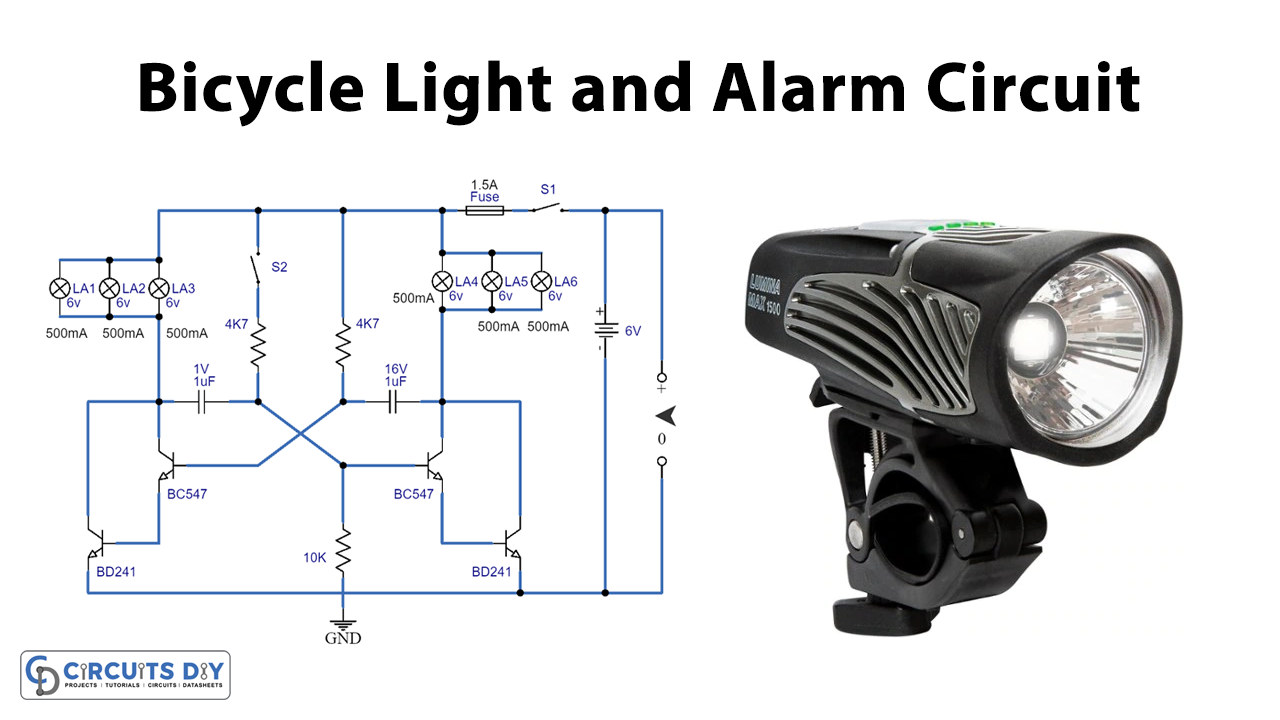
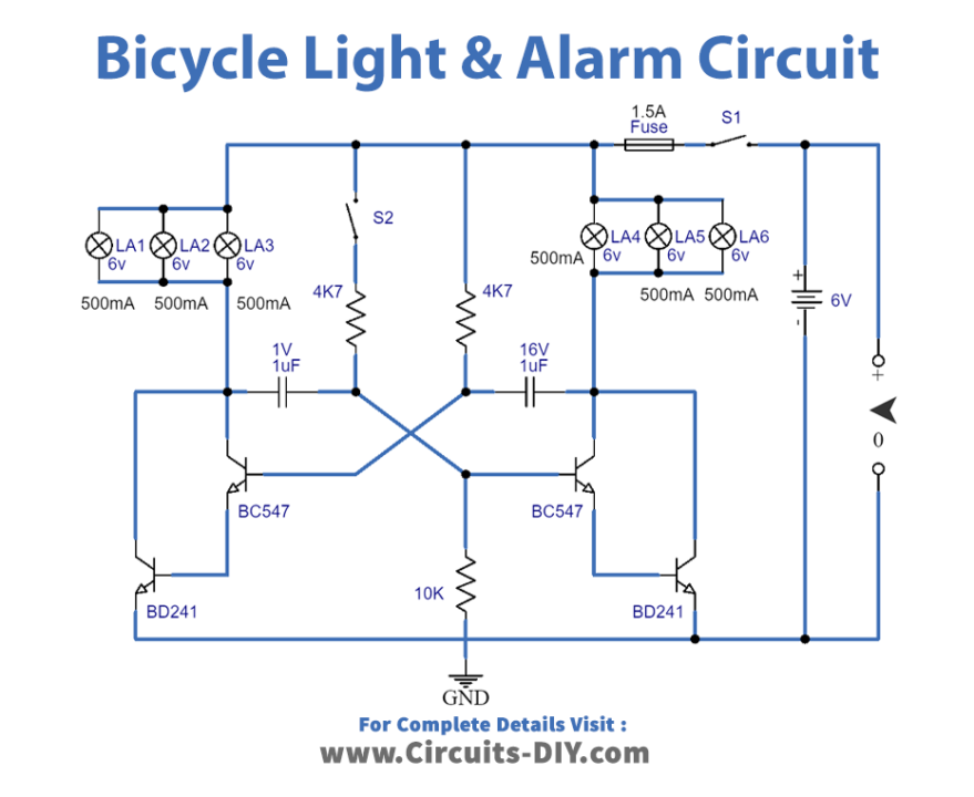
Circuit Diagram
Working Explanation
This circuit comprises an astable multivibrator, an alarm switch, a 6V battery, and lights.
When the alarm switch (S2) is open, the circuit remains inactive, so the lights on your bike will not turn on. But when the switch (S1) is closed, your bike’s front and rear lights will turn on and stay on.
When the alarm switch (S2) is closed, the multivibrator is activated and causes the lights on your bike to flash alternately. This is done to draw attention to the bike and alert others that you are there.
The BC141 component used in the circuit should also be fitted into a small heat sink to dissipate the heat generated by the circuit.
Charger Circuit
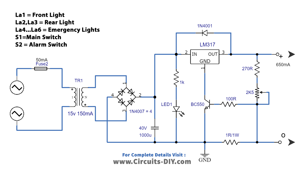
| Components | Value | QTY |
| IC | LM137 | 1 |
| Bridge Rectifier | – | 1 |
| Transformer | – | 1 |
| Capacitor | 1000uF | 1 |
| Resistor | 1K, 100R, 270R, 1R/W | 1, 1, 1, 1 |
| Transistor | BC550 | 1 |
| LED | – | 1 |
| Diode | 1N4001 | 1 |
| Fuse | 50mA-T | 1 |
Figure 2 shows is a circuit for a charger suitable for charging the battery used in the Bicycle Light and Alarm Circuit. The charger comprises components such as a potentiometer P1.
The P1 component adjusts the charging voltage to an exact level of 6.9V. This is important as the battery needs to be charged at the correct voltage level; otherwise, it will not charge properly.
It’s essential to ensure that the voltage is set correctly before charging the battery. If the voltage is not set correctly, the battery will not be charged properly, and the circuit may not work correctly. By following the given values, you can be sure that your battery will be charged in 3 hours, and you can use your Bicycle Light and Alarm Circuit without any issues.
Final Words
In conclusion, the Bicycle Light and Alarm Circuit is a valuable and practical addition for any cyclist looking to increase visibility and safety while riding at night. The circuit is simple to assemble and easily integrated into an existing bicycle lighting system. The alarm feature provides an added level of security by alerting others to any tampering or attempted theft of the bike. This circuit is a cost-effective and easy way to enhance the safety and security of any bicycle.